Leaderboard


Popular Content
Showing content with the highest reputation since 08/05/2010 in Posts
-
You can create a struct that contains the information structure that you want to pass to the UDFB. It is more logical to pass a struct with 50 members other than passing 50 inputs. Think of how the ladder element that accepts the 50 inputs will look like. it will start at the benining of the screen, and you would have to scroll few pages down in order to see its end.7 points
-
Download the attached Rar file, and extract the files to UniLogic installation directory. This means that the "UniLogic Diagnostics.exe" (and all the other files) must be placed in the same directory where "Unitronics.Shell.UI.exe" is located (usually at: "C:\Program Files (x86)\Unitronics\UniLogic\") After you've extracted the files, run "UniLogic Diagnostics.exe" and click on Diagnose. Most chances that it will show "SQL Instance" as one that has problems. In case it find problems, the "Fix" button will become enabled. Click on Fix, and the program will attempt to fix the problem, and then it will re-diagnose the problems to confirm that they are fixed. Please tell me what problems it found . Also tell me if it managed to fix the problem that you're experiencing with UniLogic (that it is stuck in loading components). Thanks. UniLogic Diagnostics.rar6 points
-
So I am sure that some of you may know factoid 2 already but I decided I would share the benefit of lots of testing with everyone. In our products we use the V570, V350 and the JAZZ units to talk to variable speed drives on a regular basis. Most drives come standard with 485 Modbus as the only communications type unless you spend extra money getting optional com cards for the VFD. Two factoids relative to noise. There was a conversation that happened accidentally in the "I have a new project" topic where someone said that Unitronics was very susceptible to noise. Well VFDs make a large amount of noise and it is not always radio noise. A fair amount of the time the noise is actually contained on the local earth to where if you ground the shield of shielded cable you make your noise problem much much worse than in you do not ground your shield. The old conversation about sometimes you have to ground a shield on one end or the other or not at all must be practiced regularly. Factoid 1: I generally would not recommend one brand of product over another but 20 years of use on pressure transducers have shown conclusively that there are definite brands of transducers that work dramatically better than others in noisy conditions. If the noise is radio noise pretty much every transducer is as good as any other. If the noise is carried on the local earth ground of the machinery then really bad things happen on every brand of transducer I have ever used (list to follow) except 1. We have used: Ashcroft Murphy Pepperl & Fuchs GEM WIKA AST Dwyer (all private labeled so there is one that works) and in 100% of the cases when there is a site that has noise infecting the ground because of VFD usage there is a horrible amount of noise created (it has nothing to do with Unitronics) and there is only one cure (separate the sensor from the metal pipe is it screwed into to isolate the sensor from the grounded pipe. If you ever have a site that has what appears to have an incurable noise issue and a VFD is involved unground the sensor and see what happens (pressure sensor just unscrew it and leave is unconnected to anything metal and if your noise issue goes away your grounded piece of equipment is causing your noise issue. So what is the one sensor that seems to be impervious to noise on the grounded pipe? It is specific to exactly one model and one product type only. The SETRA 209 series pressure sensor works perfectly where nothing else will (without lots of noise smoothing). AST is second best (but not as good as the 209 series SETRA) and everything else is just bad. Unfortunately, the 209 series is not NEMA 4 rated and is only suitable to outdoor use with the help of a cover to make a 3R cover. No other model of SETRA transducer works like the 209. Just as a note (if you are not needing Class 1 Division 2) there are companies that make electrically isolated pipe union fittings (for cathodic protection) and we have used these from time to time to help customers through ground noise problems. Factoid 2: It is in the Unitronics documentation but who reads everything (or remembers it over enough time). When connecting to RS485 it is not just important but absolutely imperative that you do not connect wires to pins 2,3,4 and 5. Even if the opposite end is connected to nothing at all (except 1 and 6). What testing has shown is that if any of the other 4 wires touch each other (because you cut them short) they will make an otherwise quite communication line unbelievably noisy. Also even if the ends are not touching the wires themselves act as little antennas and noise becomes worse. How do we know and not guess at this? Because sometimes we try to do what is right and it ends up being horribly wrong. One of our techs went out an sourced a high speed modem cable (shielded with shield all the way up to a metal sheath on the plug). It was not an inexpensive cable and sounded like a really good choice. We were buying 15 foot cables and then cutting this in half to make 2 cables (other devices have screw terminals for their connections and not an RJ12 (RJ12 for RS485 to get all 6 connections) so we would cut away all cables except the two making connection to 1 and 6 at the Unitronics port. We had 70 or so with these cables out and a high percentage of the build had special drain wire considerations that had to be made to make the communication work ok. New project with a different brand of VFD has come along and we build our first three units and zero of them would communicate over 485 communication connection. (we tested everything before build and it worked) WHY? The cable we were using had 4 sets of twisted pairs inside the shield (so two wires were not connected on either end). Testing on a V350 showed that as long as we had a computer connected to port 1 communication between the PLC and the VFD was fast and excellent TX/RX accuracy, but as soon as we disconnect the computer from port 1 communications would fail to a rate of about 75% packet loss (at slowest communication speeds). We tried different grounding of the shield to no effect, we replaced cables (didn't expect that one to work) to no effect, we took the test VFD from our desk and replaced that VFD with one in the constructed panels (no effect), so then just because there was nothing else to try we took one of the connectors that comes in the box for the V100-17-RS4X Modbus adder card and just twisted that to a standard 3 wire Beldon (really poor connection) and communication success went back up to about 99%. So we soldered 3 of the connectors from the V100-17-RS4X and shrink wrapped it all so that we could ship the 3 panels to their end customers. Then began the process of figuring out the whys and wherefores as to what the heck was going on. Taking new (expensive shielded) cable we stripped multiples back all the way to the metal cased plug and found that the manufacturer had done a good job on construction. We removed just the two wires that were not connected to anything on either end and found that removal of the two unconnected wires help com success rise to the 60% level. Then made sure that no wires were touching out of the remaining 4 unconnected wires and coms rose to a 90% success rate. Then we cut the 4 remaining wires to be about 1 inch long and made sure they did not touch anything and coms rose to about 96%. Then made our own cable with an RJ12 connector to have only 2 (totally unshielded wires with low twists per foot) wires and comes were great. So now we will be buying specialty cables that have only the two required conductors inside them. Thank for reading and I hope our pain can save you some. Keith5 points
-
Sadly not my joke....... My wife asked me why I was whispering in the house. "Because Mark Zuckerberg's listening," I whispered. She laughed. Alexa laughed. Siri laughed. 🙈 cheers, Aus4 points
-
I was contacted about how to connect the HSO outputs on a V130 to control a not-to-be-named brand of servo. If you're controlling a servo / stepper with the HSO outputs you're going to be giving it pulses and direction, so it's effectively a stepper. A servo controller has the added bonus of position feedback, but that's not important for this discussion. I tried to quickly find a post on the forum that covered properly connecting an HSO to the pulse input and I had a hard time finding what I really wanted with the forum search function. I decided it was a topic worth posting and pinning. Here's a pretty typical input to a servo / stepper control: The people who put these diagrams together assume you will be pushing the controller with a 5V line driver, which is why it's shown like this. The connection shown above tells us nothing about how to connect this to a PLC system. If you try to drive the PULS and SIGN input with 24V PLC signals you will blow this thing up. When you're connecting components together from different manufacturers, you have to have an understanding of basic electricity. There's no way around it. Ohm's Law combined with Kirkoff's Voltage Law (sum of voltage drops = 0) always wins. Let's dive in with some basic facts about optocouplers. This is the optocoupler part: It works by passing current through the LED which makes the LED light up. That turns on the transistor, which is made so that it's optically sensitive. Notice I said CURRENT. LEDs will start working after some forward bias voltage is applied and then get brighter as more current is supplied. The voltage drop will remain about the same, and eventually if you apply too much current the LED will burn out, just like a light bulb. A typical absolute maximum input current for an optocoupler is 50 mA. I always use a voltage drop of 1.2V and a supply current of 10 - 20 mA for optocouplers. Now let's look at the above circuit designed to run on a 5V pulse input with it's internal 150 ohm resistor and apply math: As you can see, the current going through the optocoupler i is 25 mA. Well within the specification. Moving on, the Unitronics HSO output is an open collector N-type Mosfet. "Open Collector" is manufacturer-speak for "we didn't connect one side of the device. That's up to you." They do this to get the speed needed to call it a High Speed Output. That's another discussion. Just think of an NPN / Open Collector / Sinking Output as a relay contact to 0V. You've got to provide the high side. Here's how the servo / stepper gets connected to the HSO Output: I've re-done the voltage equation to include the extra parts. For bonus points you can see if you can come up with the equations yourself. In addition to connecting the parts together correctly, an extremely important component in the circuit is the pull-up resistor. Let's say you're trying to hook this up and your boss and/or customer is riding your butt and you don't have a resistor. So you just connect your +24V to the (+) on the servo and connect the rest as shown. Let's do the math: i = (24 - 1.4) / (0 + 150) = 150 mA You will blow up the servo, the PLC, or both probably after about 10 pulses. Less if your output gets stuck on. If you've read my other posts on connecting stuff to open collector outputs you may remember that my go-to resistor I carry with me is a 2.2K (1/2W). Let's put a 2.2K resistor in for Rp: i = (24 -1.4) / (2200 + 150) = 9.6 mA Right in range. Yay! For the answers to these and other impossible questions remember that Google is your friend. Joe T.


 4 points
 -
I ran face-on into an application where I wanted to concatenate the time and date into one string. The RTC to ASCII function in the examples considers every permutation of Date OR Time, but not both. I tried following my own advice and using the Insert String function but it didn't work the way I thought it did. I studied the RTC to ASCII example and realized the best way to manipulate strings is to make use of buffers, controlling exactly where characters land using the Copy Tag to Buffer, Fill Buffer, and Copy Buffer to tag functions. The thing that worked best for me was to start from scratch and write a generic Concatenate function that takes two strings as arguments as well as the number of spaces wanted between the strings. I only need one space, but this could easily be modified to pass the separating character to it. I'll leave that as an exercise to another. Enjoy. Joe T. Concat.ulle4 points
-
🤣🤣🤣 Oh boy, that summarizes mi entire experience with Unictronics. Don't get me wrong the hardware is amazing for the price and there is a lot of flexibility on what can be done.. but I keep being constantly frustrated with those simple thigs4 points
-
Hold Ctrl+Shift while you double-click the Visilogic icon. This will reset the window settings to factory default. Hat tip @Joe Tauser4 points
-
I found a solution to this problem (it helped in my case, I was programming on another computer and at home project opening the same error occurred) The solution is as follows: 1. Open the project, do not click "OK" in the dialog box. 2. Open Task Manager, and shut down VisiLogic. 3. Restart the project, use recover, and click OK 2 times (in 2 dialog box). 4.Your project is open.4 points
-
EDIT BY MODERATOR: Kikis CAN NO LONGER SOURCE THIS UDFB, SO THE POST IS BEING REMOVED BUT THE LABEL RETAINED IN CASE SOMEONE IS REFERENCING IT SOMEWHERE.4 points
-
Hold Ctrl+Shift while you double-click the Visilogic icon. This will reset the window settings to factory default. Joe T.4 points
-
If it is really bad I've been known to hang an electrolytic capacitor between the analog input and 0V. I'm not kidding. Something like 10 uF @ 25V. Joe T.4 points
-
Shift+Enter to start a new line.4 points
-
The USB in the UniStream acts as an Ethernet card (while in Vision PLC, it acts as a serial port). The USB of the UniStream is an RNDIS device, and for getting // assigning the IP address of the PLC over the USB-Ethernet an uPnP protocol is used. If the firewall blocks the uPnP handshake between windows and the PLC, then UniLogic will not be able to get the IP Address and communicate with the PLC.4 points
-
Ok, managed to find the problem, here's the solution if others will encounter my difficulty: "capture image" FB only gives filename of the saved capture, to show the image in a fixed image element filename has to be completed with the folder structure in which it is contained (in this case "Media/Camera/").3 points
-
@Cara Bereck Levy Take a look at this post, especially near the bottom- If you look at the post reference chain within thus post you'll see that the question of reading floating point values from energy meters is a very recurring theme. It's a common occurrence for word order is always backwards from what Unitronics is expecting. Ask the Creators how hard it would be to add a new type of Operation to the Registers tabs for function 3 and function 4 - "Read Holding Registers Swap Words". If you look at the Official Modbus Protocol Specification- https://modbus.org/docs/Modbus_Application_Protocol_V1_1b.pdf Search for the word "float" you will find no references. This means the byte order of an IEEE 754 floating point value is not specified anywhere and repeated questions on the forum point to the fact that it's kind of the Wild West out there as to how various manufacturers decide to implement it. Unitronics would benefit from making this easier for the end user, as many of them are unaware of this issue. This dovetails with the release of the new UniClould product as we've seen energy meters are a common addition to a UniStream system and that data will certainly be desired on a UniCloud dashboard. Just my 2 cents. Joe T.3 points
-
This is where I found out there's literally no end to how much I/Os you can cram into a V570. The year is 2011, my first medium-scale PLC project. It was an animal food production plant. There was about 200 I/O points at first, and later the system grew to about 250. Also numerous weighing scales and temperature measurements. When I found out that there would be no way to put any more than about 100 I/O points via Unitronics modules, I had to resort to Turck's CANopen I/O modules. These pack a respectable number of terminal blocks per square inch of panel space. It all worked flawlessly, and in later years 2 additional I/O stations were added. Still it couldn't saturate the V570. Scan time under 10 miliseconds. Of course there would be no easy way of managing everything from the V570 screen, so a Z-View scada had to suffice. Over Ethernet the update time for 1700 tags (not monolithic, but scattered all over memory space) is about 0.4 seconds. One remark: the screens are really ugly -- back then I was sloppy and didn't know what "Snap to Grid" meant. We've all been kids once I guess.


 3 points
 -
Not Sure if I should put this here in the new "HMI Design" or in "Tips & Tricks".... Recently, an old co-worker of mine questioned me on how I had done a Screen Saver/ Blank Screen on a project I did several years back, I made this example for him and figured I'd share it here... Obviously, I started with just a Display with a black background, and nothing else on it. After a preset time of no touchscreen activity, the logic Loads this blank display. And touching the screen brings it back to the Start-up Display (or where ever you want it to go). While that worked, in the dark the display had a glow from the LCD Back-lighting. This example shows a method to dim the back-lighting on the blank display, and back bright when returning. I've commented each net to explain the logic... I imagine this has been covered elsewhere on the forum, but here is my example... JohnR ScreenSaver Display Blanking.vlp3 points
-
I recently started re-arranging my home workshop (retirement is wonderful)... And I run across things that haven't seen the light of day in decades... I dug out this old (late 50's vintage) EICO VTVM, it was given to me by an old ham radio guy back in the early 80's. I used it for a while back in my youth until I could afford something better. I plugged it in and let the tubes warm up, then took some measurements comparing to my DMM, gross differences... I got online and actually found a pdf copy of the user manual which included schematics and the calibration procedure. In the manual I was surprised to find that while it was line powered, there was also a "flashlight battery" inside for the Ohms scale. I opened the case expecting to find a corroded battery mess, but all was fine, and that old battery still read about 1V. Eveready Super 99, "the battery that doesn't know when to quit", with a price mark of 35 cents...


 3 points
 -
A neurologist was diagnosing a patient who lost his ability to do basic math. "What’s 9 plus 9? 12. What’s 8 and 8? 10. The doctor shook his head. Very interesting. What about 6 times 5? The man thought for a second, and answered 1E. Aha, I’ve figured it out! The doctor said, "Somebody’s clearly put a hex on you".3 points
-
Actually, there is a way to have a psuedo-popup window. It's done using a little-known and poorly documented system bit - SB 25 - "Do not draw display background". I used this for the PID tuning window on an oven project. I used a V1210. Here's the display with all the loops called "Setup" called from another screen. Pressing any one of the "Tune" buttons set a different bit in an array: I have code that watches for one of bits to go on and call this rung: You will notice that the description from Unitronics for this bit is flat-out wrong. The actual operation can be found in the Help if you search for "SB 25" (include quotes). Which pops this display without drawing the background- Giving this- Note the PID Tune is now the active window and is modal - nothing on the Setup screen will respond because it's not active. I have code that uses pointers to interact with the variables on the Tuning display that is not important for this discussion, but leaving the tuning display is simple: By calling the Setup display again without SB 25 set it just blows out whatever display is there, which is normal behavior. @Patrick - I would not call this "simple" in UnitronicsLand and the suggestion of others to just call another nearly identical display is what I would normally do. I used it in this application because I needed a way to indirectly interact with a window instead of creating 22 slightly different instances of the same thing. Joe T.


 3 points
 -
I think most of you probably already know the first rule of the Assumption Club.3 points
-
Twitter asks what I'm doing. Facebook asks what I'm thinking. Google asks where I am. The internet has turned into my mother. 🕵️♀️3 points
-
I had a Hyundai Santa Fe once upon a time that strangely had the calendar date displayed on the dash. It was set with the month day and year and knew which years were leap years. However, the subroutine that it went into to allow February to have more than 28 days failed to have an exit. So, on leap years it would continue to count up from February 29th, each day incrementing up. It was easily fixed by resetting the date to March 1st, but I had to see what it would eventually do. Each day it incremented up until it hit February 99th, and since there were only 2 digits, I couldn't wait to see what it would do the next day. You would have thought that maybe it would go to 00, but it didn't. It completely lost its mind and displayed nonsense symbols every day thereafter.3 points
-
3 years ago I knew nothing about PLC's. Because of people like @Ausman, @Flex727, @Joe Tauser and others on this forum, we converted 8 machines from old relay logic to PLC's with automation, made 2 pieces of complex laboratory test equipment for the lab, and entire tank farm controls that include, levels, filling, heating/cooling, mixing etc. I could have never done it with their help. I don't know if they're paid or not, but I will tell you they are priceless. I hope that @Cara Bereck Levy will show this to the powers at be so they understand the caliber of people they have in this forum. It burns me, me when people are rude or "expect" someone to write their programs without giving it any effort first. Be polite, give it your best effort and people here will jump in to help you. This concludes my diatribe.3 points
-
Yes, it was already implemented and would be available on the next release of UniLogic.3 points
-
Hi HexMan, This option exist for the enhanced models – Please make sure to use the latest OS: 1 Set in SI165 the start address of MB the user will be able to access 2. Set in SI166 the end address of MB the user will be able to access 3. Set in SI167 the start address of MI the user will be able to access 4. Set in SI168 the end address of MI the user will be able to access 5. Set SB305 to activate the MODBUS limit. For example if you will set the following: SI165 = 1000 SI166 = 1999 SI167 = 1000 SI168 = 1999 SB305 = 1 The MODBUS master will be able to access only to MB1000 – MB1999 and MI1000 – MI1999. If anyway one tries to access the restricted operands SL46 will increment. You have to arrange MIs and MBs in sequence. There is ni separate limitation for read and write. B.R.3 points
-
Just for fun, this is the control panel for a new force tester we created. If you are a Star Trek fan. I can't be the only nerd on this forum, am I?
 3 points
 -
Hi all, This Topic will list items that are worth an easy find, are odd things that standout, but are not quite "pinnable" on their own. If we pin everything that is useful, it will all become one big mess on page 1 (or bigger!). I suggest that if you want something added to the list, contact myself or another mod to have them edit it into this existing list that I see as having carefully considered updating. To save space, only links will be shown, not full previews, with the Header or a Description listed before the link. Sometimes the link will take you to a particular post within a Topic that is the answer, but a full topic read will never go astray....history is useful. It is also worth noting that this has not been written in plc talk----hence no item 0. 😉 Just a link to the Help Centre, which perhaps many people don't know about. The link actually goes to the Vision/Samba firmware update troubleshooting page, but you can easily back out of there using links under the Help Center heading to find many other topics about all things Unitronics. https://support.unitronics.com/index.php?/selfhelp/view-article/visionsamba-firmware-upgrade-troubleshooting HSC resets DW counter after power-cut http://forum.unitronics.com/topic/6118-hsc-resets-dw-counter-to-after-power-cut/ Multi Monitor (things disappearing) Issue http://forum.unitronics.com/topic/5827-multi-monitor-issue/ Setting up EX-RC1s (particularly Joe's explanation at post 9.... 21520) http://forum.unitronics.com/topic/4165-setting-up-two-ex-rc1/?tab=comments#comment-21520 Run Multiple Instances of Visilogic etc and making good use of this ability. http://forum.unitronics.com/topic/4015-multiple-connection-live-checking-tip/ EX-A1 vs EX-A2X Connection cable differences. http://forum.unitronics.com/topic/58-ex-a1/?do=findComment&comment=26267 Trend Disappearing in various scenarios. http://forum.unitronics.com/topic/5233-v700-trend-disappearing/?do=findComment&comment=22704 Many Screen Elements makes PC do long refresh time. http://forum.unitronics.com/topic/6590-visilogic-9880-hmi-frustration/?do=findComment&comment=28338 Connections suddenly showing "No PLC is currently selected..." http://forum.unitronics.com/topic/6478-connection-problem/?do=findComment&comment=26158 Connection details storage tip related to no. 9. Store all evb details elsewhere. http://forum.unitronics.com/topic/5439-hiding-remote-locations-on-your-pc-from-crooks/?do=findComment&comment=21086 Great Subroutine advice. http://forum.unitronics.com/topic/7081-subroutines/ Also have a look at this Rail Power example: https://forum.unitronics.com/topic/8525-less-than-compare-function-not-powering-coil/?do=findComment&comment=35749 Intermediate Calculations Using Same Operands....great explanation from Joe for those who don't know about this. http://forum.unitronics.com/topic/7207-linearization/?do=findComment&comment=29492 Initialize & Reset might fix weird things. http://forum.unitronics.com/topic/7271-initialize-reset-might-fix-weird-things-going-on/ Explorer gets into a loop on file loading....issue & solution arose during another topic, see the bottom of this post here: https://forum.unitronics.com/topic/7888-help-please/?do=findComment&comment=33079 Network connections tip. https://forum.unitronics.com/topic/8083-set-plc-name-indirect-vector/?do=findComment&comment=33922 Scroll bar disappearing.... M$oft does it again. https://forum.unitronics.com/topic/8143-missing-vertical-scroll-bar-in-visilogic-9880/?do=findComment&comment=34137 Using MFs and Implied Decimals explained by Joe T. https://forum.unitronics.com/topic/8201-change-mf-format-in-hmi/?do=findComment&comment=34370 Can't get to your mapped drive in Unilogic or Visilogic? https://forum.unitronics.com/topic/8326-visilogic-unilogic-mapped-drives-fix-worth-pinning/ Vision etc model not showing in hardware list? 2 topics cover possible fix. https://forum.unitronics.com/topic/3632-visiologic-ver-9760-build-0-v350-35-tu24/?do=findComment&comment=36536 https://forum.unitronics.com/topic/8757-samba-sm70-j-t38-pto-function/?do=findComment&comment=36880 UDP & TCP Modbus usage useful explanation. https://forum.unitronics.com/topic/8823-question-about-using-unitronics-plc-as-modbus-tcp-masterslave/?do=findComment&comment=37288 Not a topic link as such, just a post with a zip file of lots of old Visilogic info. MAKE SURE TO READ THE PAGE'S NOTES. https://forum.unitronics.com/topic/8958-visilogic-general-info-pdfs/ Useful String Assembly Information. Direct link to Fernando's post in a topic. https://forum.unitronics.com/topic/9040-now-i-want-to-convert-string-to-integer/?do=findComment&comment=38358 Visilogic Registration issues.....some versions require registration and there is an offline method. https://forum.unitronics.com/topic/6612-registering-visilogic/?do=findComment&comment=39719 Modbus Blocking Write commands. Solution in later Visi versions. Read entire topic. https://forum.unitronics.com/topic/1359-modbus-blocking-write-command/?_fromLogin=1 Flyback Diodes and Clamping protection...I thought this was here already.....very important. https://forum.unitronics.com/topic/2735-flyback-diode/#comment-9669 cheers, Aus 🙃 (mods note, Header 16 bold strong blue, link 10 )3 points
-
I watched the attempted moon landing today with great anticipation. Sadly, there was a failure just seconds before the landing which prevented the mission from being a total success, however, I would like to congratulate the Israel Space Agency, Israel, and all the Israeli people for what they did accomplish. This was a private initiative that attempted to do something that only 3 other nations have accomplished in the history of man (and something that none of them are still able to accomplish). What they did successfully accomplish was to place a spacecraft into a stable orbit around the moon, which also has only been performed by three other nations. This was an inspiration to us all and I am certain the next attempt will be 100% successful.3 points
-
OK, Done. Next release.3 points
-
Hi All I purchased this device on ebay. The model number is "VAP11G Bridge Cable Convert RJ45" (probably many alternatives available) Cost around €15.00 Works a treat on unistream. Plug in the ethernet and power via the USB port. PLC can now be programmed with the panel door closed over wifi. Should also work with Vision but you would need a power bank or 5v power supply.
 3 points
 -
Continuity is easy - just connect +24V to one side of the wires one at a time and see if you get it on the other side. If you have a bundle to check you can switch wire feeds in with relays and make sure you only get one signal on a DI module connected to all wires. The RTD module only returns temperature from a resistance of about 25 ohms to 267 ohms. You could reverse-calculate the resistance, but I don't think this is the range you're looking for. Resistance is not so easy. Many moons ago I rolled my own ohmmeter with a DC power supply, current limiting resistors, voltage inputs on an analog module, and current sensors into another module. I was trying to measure to .01 ohm resolution on wire to make fuses and it kind of turned into a trainwreck. I learned about thermal drift of a multi-component system the hard way - I could not keep the thing calibrated. I eventually bought a really nice four-wire ohmmeter with a serial port and multiplexed it between the wires under test - the manufacturer liked it so much they asked if I would write an app note about it- https://www.tegam.com/wp-content/uploads/2015/10/AN103.pdf So this is an area I actually know a little more than the average bear about. This approach may be overkill for what you're trying to do. Can you be very specific about what you want? Joe T.3 points
-
@Arnor, I think I've found the problem. Take the dll below and overwrite the one that exists in your installation folder. Make sure to create a backup of the original dll first. Please update me if it helps. Thanks. Unitronics.RemoteOperator.dll3 points
-
I´m not sure if this fits your needs:
 3 points
 -
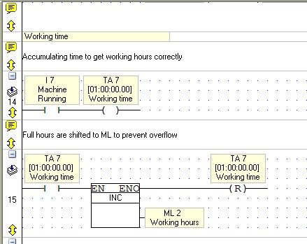
Almost the same here. The only difference is that I am using an accumulated timer for more precision:
 3 points
 -
For anyone producing their own electrical/control drawings you may have noticed the downloadable blocks in the technical library. Personally I have only ever found these useful for overall dimensions or to show the display on a general arrangement drawing. It's a shame we don't have anything showing the actual connections in .dwg (a bit like the images in the install guide). Anyway I will post here something which has helped me provide clients with a reference for connections. These are blocks and in reality the PLC connections will have interconnecting wires and all the usual stuff you would expect. I have lost count of the amount of times I have encountered the terminal number vs input/output number confusion!! Feel free to offer any thoughts. V350_Blocks.pdf V350_Blocks.dwg3 points
-
I'm convinced this is delusional. CDs were originally pretty bad because sound engineers failed to properly tailor the sound for the new media and instead used the equilization curves for vinyl with insufficient modification. That's no longer the case. Nowadays, the abysmal compression of MP3s may be worse than vinyl, but no one who really cares about sound quality should be listening to either compressed MP3 or vinyl. Vinyl necessarily has extreme equalization in order to achieve any bass response, necessarily lacks sufficient channel separation, and degrades every time the record is played. </rant> THIS I agree with wholeheartedly.3 points
-
This major release introduces MQTT, another piece of the Industry 4.0 puzzle. MQTT is a machine-to-machine connectivity protocol that runs over TCP/IP. MQTT joins the UniStream range of communication channels and protocols that supply the connectivity required by Industry 4.0 including SQL, built-in webserver that enables the controller to be accessed via any browser, and more. This release also supports new UniStream 5” models US5-Bx-R38 + US5-Bx-T42, offering new, built-in I/O configurations. Other important features in this release: HID Device support for devices such as scanners PostgreSQL support, in addition to SQL Server and MySQL UniApps localization for Korean & Italian, plus a new Korean virtual keyboard Read the version changes for more features at: https://unitronicsplc.com/software-unilogic-for-programmable-controllers/3 points
-
Great news, but twice as tall (or 50% taller) is what I need more. I have regular need for 12 contacts in parallel and constantly breaking them into two sets of six is a pain.3 points
-
What is the answer to this math problem: 7-1x0+3/3=? If you understand the PEMDAS rule you will get the correct answer of 8. However, if you just run the operations from left to right, you'll get 1. Every ladder rung in your program must be compiled to machine language before the PLC can execute the code. Do you know all the rules the compiler will use when you have a very large net? I certainly don't. Remember, like all computers, the PLC can only do one thing at a time and a large net can provide ambiguity (to humans) so the result can sometimes be unpredictable. To avoid this potential problem, always make your nets reasonably simple and break them into functional parts. It's also easier to troubleshoot and for another programmer to understand what you're doing.3 points
-
Ohh no, the old usb issues! 1 Perhaps Win 7 is now doing the W10 trick of updating drivers to whatever Msoft deems best, regardless of what the user wants/knows. I'm still on 7 and haven't encountered this yet, but I very carefully look at every update that is offered and find what it is doing. The immediate suggestion is if you have System Restore on, you should roll back to before the updates and see what happens. 2 I have had instances where a usb cable has suddenly broken a line internally. I'm assuming you have tried another known good cable in your attempts? In my instances the error messages you're getting were similar..."unknown but I know something has been plugged in." Murphy's law says that this failure is going to happen just after an update that will appear to be the culprit! 3 Have a good read of this entire discussion: In particular note the program I recommend: http://www.pro-it-education.de/software/deviceremover/ Edit: I have discovered this link doesn't work anymore. Can now be found here: http://www.softpedia.com/get/System/System-Miscellaneous/Device-Remover.shtml I have found it incredibly useful for removing dud drivers Windows squirrels away. If you haven't had luck doing 1 & 2, try getting rid of everything using it and start again from known good drivers. ONLY install them. 4 I am finding more and more devices that used to be serial connections, but are now usb in the same looking body. But lo and behold they have just added a prolific/fake chip onto the pcb so that it "looks" like the unit is usb to the user. It is essentially still serial and the onboard chip lets them get into it if they don't have serial connections available, like modern stuff infuriatingly doesn't. I have been exceptionally careful about what I allow to happen during the first insertion of any device that likely falls into this description. It is a minefield. Tread carefully! cheers, Aus3 points
-
This problem dates back to when the USB to serial adapters were first introduced. It is not a Unitronics-only problem, it's a Windows thing. I have experienced multiple instances of the same driver trying to access the same COM port when it comes to the USB interface. It is a royal pain in the butt and you have to rip them all out and start with a clean slate. The problem is you can't see them all, even if you check "show non-present devices" in the Device manager. There is an environment variable you have to set to truly "Display All Non-Present Devices". This article describes the process to get all your defined COM ports to light up- https://technet.microsoft.com/en-us/library/ff184583.aspx You probably have a bunch of stuff defined that you didn't even know about. Uninstall all the COM ports. Then plug your PLC in and see what happens. Joe T.3 points
-
Hi, even on programming languages like c# it's incorrect to show a view from code (for example a messagebox). Message boxes are usually required for a user input, and are in most cases 'code blocking' (The next command will not executed until the message box is closed, since it is waiting for a dialog result). In UniLogic, message boxes are shown in a response to a user interaction (clicks, for example), and the result of the user interacting with the message box is clicking on one of the buttons (OK/Cancel/Yes/No) is executing 1 or more actions defined by the programmer. This is the correct way or writing UI. I don't know the reason you want to show a message box, but for example, you want to show a message box like: "Temperature is over 80 deg), and you want to call it from Ladder. In that case, I would choose Alarm for several reasons; * Not blocking UI and annoys the user * What happens if the deg reaches 81 and then falls back to 70 and then again reaches 81? Should another messagebox open while an active one is already opened? * If the message box is designed to set a big when the OK is clicked, and the calling function is no longer running, what would you expect to happen? We do want our user to keep a separation of UI from logic (You won't see any "Load Screen" elements in Ladder, but we do give a Load Screen global action which can be triggered from a bit). A workaround for what you want is to have an overlay of something that looks like a message box with the texts and buttons that you want, and control it's visibility with a bit. (You can also design it as a custom control, so you will only need to set the visibility bit once, on the entire instance of the custom control) Another workaround is to design the whole message box as a screen, and load the screen when the bit is set (the global action will automatically reset the bit), and when done, use "Last Screen" action on the clicked button in order to return to the original screen.3 points
-
So I answered a post yesterday where the user was concerned that the cost of the controller was over $500, implying that this amount was putting the project out of reach. This morning a few of the things we take for granted and never question came into my mind- Decent tires for my Jeep cost about $1,000 A new cell phone costs $600, but it's a "free upgrade" because it's rolled into your next 24 payments A trip to the grocery store for a week or so of food is $300 for a family of four My furnace/AC upgrade to a high efficiency unit was $7,000 Getting my car fixed by someone else is usually about $600, no matter what the problem is. Sometimes it's a lot more. Health insurance is >$700 / month And so on..... It seems like machine controls get the short end of the stick a LOT. Why is the perceived value of what we provide so small? Systems I've installed are still running fine after 20 years! I know not every customer feels this way, but it get this response frequently with people new to control systems. I'm afraid I'm not far from becoming a full-fledged curmudgeon. Joe T.3 points
-
Set the Border Thickness to 0, and the Background Fill to transparent (by either choosing the transparent color, at the bottom left corner of the Stardard color, or by entering 00FFFFFF in the Advanced Color)3 points
-
Hopefully you've already figured this out, but just in case you haven't.... If you want to prevent other programmers from seeing a particular screen configuration, you can right click on the screen name(in the Solution Explorer), then select "Password Protect" If you want to prevent unauthorized access to the screen during operation, you can assign a button on another screen("Main Menu", for example). Then, in the Properties Dialog box for the button, add a new "Load Screen" Action, then set the User Access property. In the Solution Explore, use the "User Access Control" to configure the different levels of access, as your application requires. I apologize for not being more detailed, but I am also a new to the UniLogic platform and just started looking into the whole password protection/user access system. The more I learn, the more I like!3 points
-
Big time thanks to Joe for his support, even thuogh sometimes I bug him when I am in a crunch, he always comes thru with an answer.3 points
-
A shepherd was herding his flock in a remote pasture when suddenly a brand-new BMW advanced out of the dust cloud towards him. The driver, a young man in a Broni suit, Gucci shoes, Ray Ban sunglasses and YSL tie, leaned out the window and asked the shepherd... "If I tell you exactly how many sheep you have in your flock, will you give me one?" The shepherd looked at the man, then looked at his peacefully grazing flock and calmly answered "sure". The man parked his car, whipped out his IBM ThinkPad and connected it to a cell phone, then he surfed to a NASA page on the internet where he called up a GPS satellite navigation system, scanned the area, and then opened up a database and an Excel spreadsheet with complex formulas. He sent an email on his Blackberry and, after a few minutes, received a response. Finally, he prints out a 130-page report on his miniaturized printer then turns to the shepherd and says, "You have exactly 1586 sheep. "That is correct; take one of the sheep." said the shepherd. He watches the young man select one of the animals and bundle it into his car. Then the shepherd says: "If I can tell you exactly what your business is, will you give me back my animal?", "OK, why not." answered the young man. "Clearly, you are a consultant." said the shepherd. "That's correct." says the man, "but how did you guess that?" "No guessing required." answers the shepherd. "You turned up here although nobody called you. You want to get paid for an answer I already knew, to a question I never asked, and you know very little about my business...... Now give me back my dog."3 points


-
Blogs
-
Unitronics' Blog: PLCs, HMIs and more
- 83
entries - 45
comments - 114673
views
- 83
-
Saragani's Blog
- 2
entries - 3
comments - 12896
views
- 2
-
Simon's Blog
- 4
entries - 3
comments - 13465
views
- 4
-
Ash Neilson's Blog
- 1
entry - 2
comments - 5711
views
- 1
-
Joe Tauser's Blog
- 1
entry - 1
comment - 6480
views
- 1
-
-
Popular Contributors
-
Who's Online (See full list)
- There are no registered users currently online
