JustinCochran
-
Posts
26 -
Joined
-
Last visited
Content Type
Profiles
Forums
Gallery
Events
Blogs
Downloads
Articles
Media Demo
Everything posted by JustinCochran
-
So I connected the solenoids to the vt card yesterday. Just for safety precaution I put power to card through a push button in case it tried to move too fast on me. I started by inputting my X on analog output and it works properly. The higher the number faster it moves and same way in the negative. So I wrote the code using the 4 prox switches as stages for a different setting to be stored into analog output and it works great.
-
Yes, I did read that. Thanks for referencing it again though, I hadn't noticed that for future I can use the IO-AI2AO4 module to accomplish this without the analog converter. This is first time I've ever dealt with analog outputs. I've done several analog inputs for leak testers using pressure transducers. I still have much to learn.
-
Just want to update this topic for future reference to anyone else that comes across this or something similiar. Much thanks to Joe for calling and going over some of this and getting me started in right direction. Today I powered up my plc and used an analog output from my snap in module (4-20ma) to the analog input of analog converter box. It was already setup for 4-20ma on converter input. In coding I made X of analog output -100 to 100. I hooked up voltmeter to output of the converter. The output is setup for +/- 10v. While changing my X in program, I could see the voltage move from -10 to 10 on output of converter. I next ran wires from converter to the vt card analog input. Reading a positive voltage of any kind puts 24vdc to one solenoid while a negative voltage energizes other solenoid. I didn't have the solenoids hooked up though, just testing the output on the vt3006 card. That's as far as I got so far. Will do more testing next week.
-
I'm guessing that is what this little relay is. Haven't been able to find much info on it yet. I do know it has a 24vdc power input, 4-20 ma input and a +/- 10v output. The output went to vt card, rest of it wasn't hooked up. I'm drawing a blank on how to even begin the coding for this. Im a fish out of water on this one. Any examples of this type of control or anyone have an idea how to begin?
-
Thanks for the response. I'd like to add that there also is/was an analog relay block that has dip switches set for an input of 4-20ma, and output of +/- 10v. I know the output from this relay went to card. I'm assuming the input came from old plc system. I know I can probably use analog output from my snap on module to input of the relay. Just trying to think how I can code it to work properly. All wires that were on card are still where they went. I have the 24vdc input power, both solenoids to proper terminals, and that one input to card from the output of +/-10v from analog relay block. I have some what of an idea in my head, too hard to explain though. It involves using the 4 prox switches and increments to output. Just for simplicity, my 4 inputs are down, almost down, up, and almost up. I'm also thinking of using 4 of my outputs to control each stage. If anyone has dealt with something similar, I'd appreciate any advice on how to go about this. Thanks.
-
Hey all. I've stared a new project and am giving myself a good headache trying to wrap my brain around this probably simple problem. I have a rexroth vt3006-s-30 card controlling two valves for a hydraulic cylinder to move in and out. Looks like the old plc that wasn't there anymore may have had analog output to rexroth card. Has anyone dealt with rexroth vt3006 cards and controlling them with visilogic? My carriage that cylinder operates has 4 prox switches that I was trying to perhaps use for different stages of where carriage is. Is there perhaps easier way to control valves without the card and using visilogic program to do same thing as the rexroth card? Any thoughts? Thanks for any and all responses.
-
Nevermind I think I have a solution that I'm going to try.
-
Hello, I'm in the process of doing program for a blow molding machine. This one has rexroth vt5006 s16 r1 proportional amplifier cards for molds open and close valves. Used to have a maco 8000 system and I'm installing v1210 visi system. I'm trying to wrap my head around how to properly use cards with plc. Hoping someone might get me started in right direction. Here is what I know. Inputs to plc: Mold open prox, mold partially closed prox, mold close prox, and mold completely closed prox. Outputs from plc to card: Close mold relay on terminal 12c of card, close mold cushion relay on terminal 12a, open mold relay on terminal 16a, and open mold cushion relay on 16c. Outputs from card to solenoids: Open mold sol on terminals 2a and 32a of card, close mold sol on 2c and 32c. The cards are still wired to valves and whatever else is there except for outputs from plc to card, for now anyways. I'm more interested in the logic for controlling them. If anyone can help, I'd appreciate it. Thank you.
-
All my other inputs and outputs on the snap in module are fine. The power supply isn't the issue. On the analog inputs there is the following for each of the 3: V I 0V The 4-20 mA sensor clamps around a motor lead and has a "+" and a "-" connection. I think I may have figured out my problem, will have to check next time I'm at work. What I did was go from the + of sensor and go to V and I of ANI0 and the - to 0V. But I don't have any 24VDC + going to it. I'm thinking I need to have the 24VDC + to + of sensor and then the - to I and V and 0V going with the other commons. Now that I think of it, I forgot to give it power. It's usually always something simple, lol.
-
Something to add. When the motor I have is running or not, it always says -24 on output of the linerization block. The input bit is always 0 on the linerization block.
-
Hi, I'm using a V200-18-E1B and I have an analog input from a 4-20 mA amp gage. The problem I have is the reading I get is always a negative number. Instead of seeing 22 it's -22. I have it set up in linerization where x is 204-1023 and y is 0-100 representing a %. I have a common 0V going to 0V on the analog input. I jumpered V and I together and connected one side of the amp gage to that and the other to the 0V. Am I doing something wrong? I keep looking over the specs and how I configured and I'm drawing a blank. Justin
-
Hello, I recently got a new laptop and I'm trying to save my projects from one laptop to a flash drive, so I can save them to the new one. However, when I try it keeps saying the following: "An open project cannot be saved to a removable storage device such as a disk on key. Once project is complete, it may be copied to such a device." So I guess my question is, how do I make it complete, or how do I get around this? Thanks Justin C
-
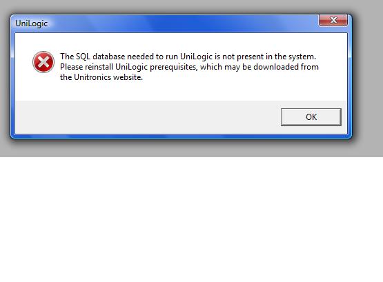
VisiLogic Error
JustinCochran replied to wildweasel's topic in Vision & Samba PLC + HMI Controllers & VisiLogic Software
I don't remember if I even put the link to the page I used in my post, since a mod has to approve mine anyways. Just in case I did forget, here it is. http://forum.unitronics.com/index.php?/topic/2517-uni-software-installation-in-windows-8/ -
VisiLogic Error
JustinCochran replied to wildweasel's topic in Vision & Samba PLC + HMI Controllers & VisiLogic Software
I had the same problem and I have vista. Check the link below, I used that way to fix my problem. I didn't have to disable UAC though, I omitted that step and it worked fine for me. I did however have to go to properties and unblock it, and also make it "run as administrator". On my PC the admin user is what I use. Hope that helps. Justin -
I have tried to intall the unilogics software on my personal PC 4 times, first time I ended up changing the UAC since I use vista. Now it gives me this same message. Each time I uninstall everything and redownload it, then install again. Once it's done and I say yes start unilogics, I get this message. Am I doing something wrong? I downloaded and installed on a laptop that also had vista with no problems.

-
High Speed Outputs and PID
JustinCochran replied to JustinCochran's topic in ...I have a project...what hardware do I need?
Wish I could edit my post I submitted before this one. I'm thinking the frequency is probably the cycle time, correct? -
High Speed Outputs and PID
JustinCochran replied to JustinCochran's topic in ...I have a project...what hardware do I need?
I don't see where you would change the frequency unless I configure a HSO on, for example, the snap in I/O. As far as what I have so far, I'll explain as best as possible. I have a MB that triggers PID autotune RUN, if it is not in the process of auto tune, and the status of PID is greater than or equal to 0. After that, I have the PWM scan FB where I put a number of 400 for cycle time (just made one up for now, not sure as this is all hypothetical right now), and the duty cycle is PID: CV - the PID output. The result MB triggers a relay that lets power go to the heater band. Probably would be a solid state relay or maybe a different type. Does that look like a step in the right direction? Thanks. Justin C -
High Speed Outputs and PID
JustinCochran replied to JustinCochran's topic in ...I have a project...what hardware do I need?
Another question I thought of using auto PID to calculate the PID parameters. Say I end up using 10 loops, can I use one PB to auto tune them all at once or would it be better to use a different start up procedure for each loop? Is auto tune something that has to be done everytime a machine with heating controls has is turned on? Or is it only have to be done once to find the parameters, then it never has to be auto tuned again? If I do end up doing this application on a machine it would probably be turned on once a week and stay on for 5 days before being powered down. Thanks Justin C -
High Speed Outputs and PID
JustinCochran replied to JustinCochran's topic in ...I have a project...what hardware do I need?
Thanks for the reply Joe. Once again it is very helpful. From what I understood, PID keeps the temperature close to the setpoint or pretty much right on the setpoint. In the application I would use it in, I would be heating up a heater band that is wrapped around a steel barrel that melts the plastic inside it. Typical heater bands we use are single phase 240 V, the wattage varies. Temps would be about 350 degrees F. I would want to think I would have to use PID on all my loops to keep the temperature as close as possible. The applications I have seen that use a typical heating controller, the temps are always within a degree or so of the setpoint. I was actually looking at examples earlier that dealt with both HSO and PWM blocks. That was actually going to be my next question if PWM blocks would work for this. I was hoping that would be the case. Justin C -
Had some questions involving using about 10 to 12 seperate heating controls. I watched the webinar on PID and that explained a whole bunch, but not everything. I noticed in the example in the webinar he used a high speed output to control a solid state relay if I'm understanding that properly. When using PID and heating is using a high speed output a must for this application? I was just looking through the different I/O expansions and wasn't seeing anything that had more than 1 high speed output. Is there one I'm just overlooking or is there a different way to go about this? I don't actually have a project, just doing some different examples on my own time to learn and understand more. Maybe in the future and hopefully this will play a part in a project that I'd like to do. Justin C
-
I ended up using a counter that is reset each time the power is turned off and on again, or when it reaches 9999. That way they could reset it if they wanted to by just powering it up again. Using spray type bottles I was able to get 27 bottles a minute tested. I might be able to get it even quicker but that exceeds expectations. The V120-22-R1 I looked at before did the job perfectly. The dwyer pressure transducer for 0-5 psi did the job great too. Thanks for the help you guys gave me, made it much simplier on my part. Of course this was a rather simple project compared to others, but it's a start in the right direction.
-
As far as defining my leak test, I basically have all the steps I want it to do. I know exactly what I want it to do. I have been writing and changing the logic for a couple days. Everytime I re read it, I find a small problem I over looked. I think I just about got it this last time. It's a good learning process. Instead of making a new topic, I might as well ask this here too. I wanted to put a counter on the main screen showing the total bottles tested. My question is, is there a way to reset the counter value once it reaches the max of 99999? Does it start over once it maxes out? I couldn't find my answer in help documents. Thought about just making it a preset value by using the keypad and resetting it manually. I wanted to avoid that if possible.
-
Also I would have a setpoint of a known good bottle as the point to make or break the test.
-
I haven't bought the v120 yet. Want to make sure I am going to get the proper hardware before I commit to getting anything. I am nearby Kansas City, MO and we have a contact, haven't been able to here anything back from him though, which is why I came here. Not entirely sure how much air would leak from a tiny pin hole in a plastic bottle, let's say the size of a squirt bottle, with 5 psi put into it. I'm guessing that's what you meant by my resolution. Like I said in my first post, I'm not sure on what I'm doing really, this is my first attempt at using any plc or making my own leak detector. Still have a bunch to learn, so forgive me if I don't understand all that much as of now. Not sure by how to define my leak test, not sure what you mean. Only thing I can say to that is 5 psi compressed air is forced into a bottle and after a few seconds it measures the loss of the pressure since the start of the test to the end of the test. If it's too much of a loss it rejects, if it is suitable it passes. Anythng as small as a needle hole is no good.
-
I haven't wrote a program for the leak test yet. I haven't tried or know exactly how I plan to define my leak test. I do like the industrial type you referenced to me. Think I'll go that way. Now that wouldn't need it's very own power supply does it? Can I come off the 24 VDC power supply that would power my v120-22-r1 too? I see that it has a 4-20mA output, so that would take care of my problem with the hardware. The program part though, might give me a hiccup too. I'll find soon enough. Do you have any recommendations?