Apollas
-
Posts
14 -
Joined
-
Last visited
Content Type
Profiles
Forums
Gallery
Events
Blogs
Downloads
Articles
Media Demo
Everything posted by Apollas
-
Bumpless PID example
Apollas replied to Apollas's topic in Vision & Samba PLC + HMI Controllers & VisiLogic Software
So, if I want to force 30% of the pump speed at PID startup I have to force integral error with value 30000? 75% would be 75000 and so forth? As I understood 1% of CV value matches force integral value 1000. It always has to be multiplied by 100 in VisiLogic. -
Bumpless PID example
Apollas replied to Apollas's topic in Vision & Samba PLC + HMI Controllers & VisiLogic Software
Hello liranaftali, I'm interested just in multiplying MI10 by 100 part before forcing the integral error. All the rest is clear to me. You mentioned that parameter range is -100,000 - 100,000. I cannot find anywhere this information in VisiLogic Help docs. Why do you need to multiply by 100? That's what I'm interested in. -
Hello, I'm studying a bumpless PID example from VisiLogic > Help menu > Examples > PID. And I cannot understand why manual CV value is multiplied by 100 before forcing the integral error value in Net 7. Maybe anyone can explain. Thank you.
-
MF to DW for HMI displaying
Apollas replied to Apollas's topic in Vision & Samba PLC + HMI Controllers & VisiLogic Software
OMG! Totally forgot about MLs. Will try it today, but I think that it's exactly what I need. Thanks s.pratt. -
Hello, Here's the situation: I have V1210 PLC and I'm reading a totalizer value (float format) from Siemens MAG6000 flowmeter via MODBUS. I want to display this value, but I don't wanna use "Variable:Numeric", because I cannot chose how many decimal places to display. Actually, I don't need decimal places at all. I cannot use INV (A+B/n), because MF value is going to be larger than you can store in the MI. I need a comfy MF to DW conversion just for displaying the value. What options do I have?
-
Vision 1210 + Jazz 20-R31 MODBUS problem
Apollas replied to Apollas's topic in Jazz, M91 PLCs and U90Ladder
Hi, If I don't disable Net2 it doesn't work at all. Without it at least something works. I looked through that example, but didn't find anything useful. It's for M90, not for Jazz. I want to read/read MIs. -
Vision 1210 + Jazz 20-R31 MODBUS problem
Apollas replied to Apollas's topic in Jazz, M91 PLCs and U90Ladder
Hello AlextUT, Well, it helps a little bit, because if you are right at least I know that I cannot use MODBUS and debug at the same time I made some changes in ladder. I've disabled network 2 on my Jazz 20-R31 (Slave). Now, I'm able to write data from V1210 to Jazz 20-R31 (Slave), but I cannot read any data from it. Even if I write data to Jazz 20-R31 (Slave) successfully, I'm still getting status message #5 - No Communication. I've improved a little bit, but still it's not working properly and I'm out of ideas. Any help is needed. Regards, Giedrius K. -
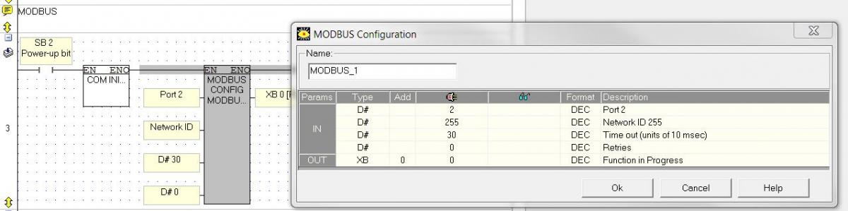
Hello, I'm trying to connect Vision 1210 (Master) with Jazz 20-R31 (Slave) via MODBUS RTU. I had no success so far. Master can successfully read other devices via MODBUS. All the settings are attached. With MJ20-PRG I can connect to Jazz PLC and download the program, but I cannot connect it to MODBUS. When I change MJ20-PRG to MJ20-RS MODBUS isn't working and I can hardly monitor ONLINE. Sometimes it's going ONLINE, but the connection breaks or most of the time it's showing that there is no connection. Looks like the connection exists, but it's very very unstable. I tried both, function 599 and 600, it didn't solve my problem. Questions: Q1: Is it possible to go ONLINE and connect Jazz via MODBUS at the same time with RJ20-RS? What Jazz PLC settings should be then? Q2: And of course, what I'm doing wrong? Thanks for you help in advance. Regards, Giedrius K.


-
Analog input signal range
Apollas replied to Apollas's topic in Vision & Samba PLC + HMI Controllers & VisiLogic Software
Thanks again. -
Analog input signal range
Apollas replied to Apollas's topic in Vision & Samba PLC + HMI Controllers & VisiLogic Software
Thanks cantcliff. The thing is that I dunno if that example I'm looking at is correct. Also, I'm new to Unitronics, so I was just wondering maybe it's a standard trick for testing an analog signal. As far as I understood it's not a common thing to do and this example might be working properly or might not. Also, it could 191 instead of 190, it wouldn't make a difference, because it's below 204 anyway. -
Analog input signal range
Apollas replied to Apollas's topic in Vision & Samba PLC + HMI Controllers & VisiLogic Software
I've already checked those pdfs and I definitely couldn't find the values that I mentioned. The info about it is really poor in the specifications. None at all or couple of sentences about OUT OF RANGE, but nothing about the exact values or how to calculate them. -
Hello, I'm studying an example project and I found one thing that it's not crystal clear to me. It's about analog inputs. MI0 is a 10-bit 4-20mA analog input, so you have to use 204 to 1023 (820 units) for the linearization. In the net above it, it's checking whether the signal is between 190 and 1040. I believe it's checking for underflow/overflow. But why 190 and 1040 values? Why those values are used and not others? Same situation with MI6, a 12-bit 4-20 mA analog input. 819 to 4095 (3277 units) for the linearization and 800/5020 for the underflow/overflow detection. Maybe those values in the example are not correct. So, my question is how do you calculate analog input values for the underflow/overflow detection. In Siemens there is a table with those values (see attached), but what about Unitronics? I wasn't able to find such table. Regards, Giedrius K.


-
VisiLogic message
Apollas replied to Apollas's topic in Vision & Samba PLC + HMI Controllers & VisiLogic Software
Thank you. Looks like it worked, but I need a little bit more time to be sure that is really OK now. It really sounds a bit complicated as just for the normal program installalation -
Hello, When I open a project or close Hardware configuration I'm getting a message that says: prvChangeGuiByPLCType 9Invalid Tools collection index (attached). I'm new to Unitronics and I have no idea what's wrong. Thanks for your help. Regards, Giedrius K.