

liranaftali
-
Posts
12 -
Joined
-
Last visited
Content Type
Profiles
Forums
Gallery
Events
Blogs
Downloads
Articles
Media Demo
Posts posted by liranaftali
-
-
In addition I recommand you to check for any loops in the application , you can do it using the on-line mode.
-
Hi,
What I recommand you is the following:
Turn OFF the PLC-->click and hold the touchscreen-->turn ON the PLC (it will enter to factory mode-->check the communication PLC to PC.
If there is communication: update the PLC OS:follow the below procedure:
-
Go to connection menu>Communication & O/S> 4th tab check the current version> in the opned window: click on 'next' buttins in order to download OS to the PLC.

-
-
Hi,
I attached here a simple and working example of sending SMS to multiple numbers using DT.
Just make sure to:
- Change on net 5 the greater than block according to the number of phone numbers you wish to send to.
- Add the numbers to the DT and download it to the PLC via the 'write values to PLC' button from the Data tables top menu.
-
 1
1
-
If you mean remapping the Vision memmory, so it is not possible.
If you meant the SCADA, you supposed to be able to read or write to any permittted address.
-
Hi,
What do you mean by copy the 30000 register into the 40000 register?
-
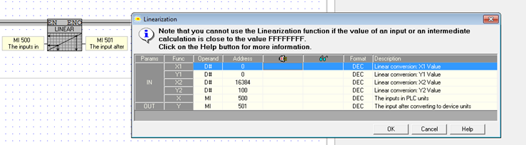
Hi, So both analog and digital are inputs to the PLC from the Flow Meter, If this is correct and the digital input does'nt have to be used, you can use only the Linearization block without the ADD block, and you will get the input from the Flow Meter every scan How to create a linearization (example is attached): The Linearization setting (also in the attached image): 1.First you have to check the resolution of the specific PLC(in the SPEC), for example the V350-35-R34 is 10-bit and it will be, 0-1024, so X(1)=0, X(2)=1024. 2.Y(1) and Y(2) will be the units from the device itself, for example 0-100. 3.In X you will set the register that getting the inputs from the device. 4.In Y you will set the output of the from the ‘Linearization’ block. *If it is still not clear, you can share the device SPEC,
-
Hello,
If I understood correctly, using the analog output you are turning on and off the valve? and using the digital input you are measuring the flow? is that correct?
Can you share the Flow Meter SPEC?
-
That's probably not as accurate as you described it,
I recommend you to run a few experiments in order to get your required result.
-
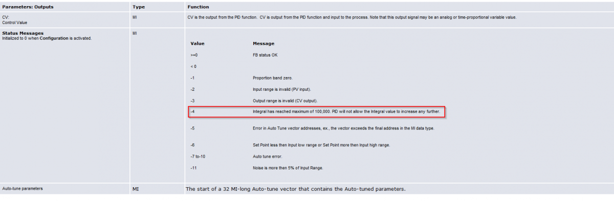
Hello,
The Multiply by 100 is only in order to get to 50,000 and closer to 100,000 (max value),
and by that to prevent the "bump" in the PID.
I attached a screen shot of the help of the 'PID A.TUNE config' status messages.

-
Hello,
'Error Integral' is the parameter that controls the PID correction,
This parameter range is (-100,000 à100,000).
In order to prevent "bump" on the PID correction, in this application the 'Error Integral' start value is 50,000,
That is done by using MI10 (power up value: 500) multiplied by 100 in the function block and store it in ML0 (net 7).
ML0 is the 'in parameter' to the "PID A.TUNE FORCE ERROR INTEGRAL" block and as a result the steep "bump" is prevented in the PID.
I hope you find this information useful.


Schedule daily and monthly data record
in UniLogic Software
Posted
Skout,
The solution on UniLogic is different (what mentioned on the last post is for VisiLogic),
As you mentioned the trigger for saving the DT to the SD can be using a schedule.
Now, in order for the file name to contain the date and time you will need to use the attached RTC to ASCII UDFB (there you will select what kind of data you will get in the output of the UDFB), you can get more information in the UDFB comment.
In you case you will need to call the UDFB twice, first for the date and then for the time , then you will have to use the 'Insert string' element in order to create one string from both of the strings, and attach this string to the file name input, when saving the file to the SD.
I also attached a short example that uses the UDFB.
*In case you wish for some more information regarding the UDFB, you can view the UDFB webinar on the Unitronics website.
Hope it helps.
DT_date&time_Writing.ulpr
RTC to ASCII.ULLE