

tonymony
-
Posts
63 -
Joined
-
Last visited
Content Type
Profiles
Forums
Gallery
Events
Blogs
Downloads
Articles
Media Demo
Posts posted by tonymony
-
-
Hello,
I am currently working in a project with expansion modules IO-DI8-TO8/RO8. All my expansion is full I have 8, could I change one of the IO-DI8-TO8/RO8 for one IO-DI16 to increase the inputs number?
Thanks,
-
Hi Ausman,
Basically I am checking and improving. I working with a input which is refreshed each 2 seconds by a pulse.
KR,
-
Hi,
I finally solved my problem with these ladder logic. I will test tomorrow the performance.
I know I can delete some elements but I prefer add all the blocks and check the process one by one.
Now my question is how to convert a Memory Float in seconds to hours, minutes, seconds.
KR,
-
Hi,
Cheers for your answer and the detail of 2 sec, the problem for the signal configuration it is because by default if you have a shut down the flow meter read, (Flow and Pulse).
Then my question is there how to introduce the pulse in my programming, like a high speed input? or a normal input?
KR
-
Thanks Gabriel,
Gracias desde Medellin
")
-
Hi,
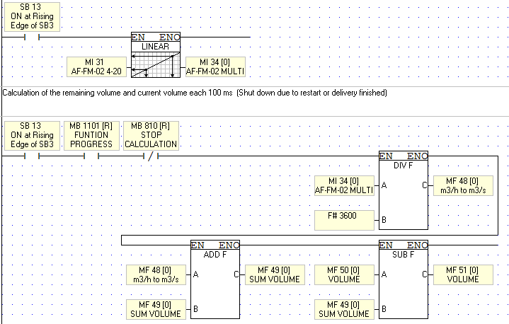
This actually what I finally thought about how to convert from m3/h to m3 in a refreshing range of 100ms. So basically if it works like I think the sb7 works.
- Linearization 4-20mA to 0-1181m3/h
-
Scan each 100ms if the proccess botton is close do the next routine each 100ms:
- Flow rate in m3/h to m3/100ms
- Summation the current value+the previous value
- Volume requiered-Summation=Volume Remaining
- When Volume remaining <= 0 then activate routine finish delivery and open the process botton
I am not actually sure about how this sb7 works. I will be wonder for anysuggestion, thanks for your help.
Regards,

-
Hi,
Sorry I mean analog input, one is a pulse and the other one is a normal 4-20mA. Yes I would like to check each 0.1s the volume so is refreshing each 100 ms.
KR,
-
Hello,
I am currently checking an installation of a Flow meter model: Hoffer HIT-2A.
I would like to calculate in my PLC the Volume flowing at real time. This kind of valve has 2 outputs, 4-20 mA for the Flow Meter and a Pulse with 62.5 msec signal.
Should I create a High speed input or can I use the next structure for the Volume Calculation in real time.
Any suggestion?
Thanks in advance

-
Hi Joe,
Basically, I have all my digital inputs full and I need to add a new one for an alarm which is 0 or 1, I supposed I need to test the current when the alarm is on and make an interval to consider this MI like an MB inside the program.
KR,
-
Hi Sirs,
There is anyway to convert an analog input to a digital input?
KR,
-
Dear Sirs,
I am trying to set up Alarms, and reset all of them but I have got some issues, today is 12/07/2016 but my alarms are showing another date.
 Thanks
.
-
I have attached the program in this like, is like a littler simulator, but it does not work. I do not know how this bits are on.
https://drive.google.com/file/d/0B2KvxQP-uoqGRksyWUNRZGRoQ00/view?usp=sharing
-
Hi Sirs,
I rethink all the ladder logic, I would like to ask you if you notice at first look anything wrong, with ladder logic's LOGIC
I have the next pieces working. I am going to start working with a normal routine(Basic), generator 1 Day, generator 2 Night, generator 3 Standby and a transformer which is the main one.
I am simulating this program with bits instead with inputs and outputs.
I have the next componets:
Generator 1 start is MB5
Generator 2 start is MB6
Generator 3 start is MB7
Phase failure rele transformer is MB0
Phase failure rele Gen 1 is MB10
Phase failure rele Gen 2 is MB11
Phase failure rele Gen 3 is MB12
Breaker Switch Transformer is MB1
Breaker Switch Gen1 is MB2
Breaker Switch Gen2 is MB3
Breaker Switch Gen3 is MB4
Gen routine BIT MB8
PFR House MB9
BUSBAR Alarm MB13

This is my program idea, I will performance and I will simulate. Could anyone say me if there is some confict condition with ladder logic in this program?
Thanks
-
Hi Sirs,
Do you recommend me any logic with this plc to do time cycles?
It is very tedious implement the code, even with one routine.
KR,
-
Hello everyone,
I am come back to the forum since too much time. I come back to Unitronics' PLC programming and I have got an issue with a routine.
I am currently working with a generator routine which looks like:

We have a panel with 9 bottons to select a state for each generator (Day, Night, Standby). Therefore we have 6 combinations:
- Day,Night,Standby
- Night,Day,Standby
- Standby,Day,Night
- Standby,Night,Day
- Day,Standby,Night
- Night,Standby,Day
And if it is not any of these ones,it will work with this state like standard one: ''Day,Night,Standby"
Now the problems come. Time functions:
Day-07:00-19:00
Night-19:00-07:00
Standby should work when there is a failure in one of the other ones.
I made a simple visual checker with 3 pictures simulating the state of the generators, but I do not know why routines Gen1,Gen2 and Gen3 are always "ON".
I have attached the file in this link.
Thanks for your help. -
Thanks Flex
, it was very useful.I have a nother question I realise the webserver is simple, I read about a advanced webserver method, but I got the Visilogic app but it didnt work it has a password. It is in this link. http://www.unitronics.com/support/plc-tools-and-application
Complex WebServer
Special thanks to our forum member zpy, and also to Nacho for testing
This .zip file contains everything you need to enable an Enhanced Vision with an SD Card to serve complex pages. Click to download...This .zip file contains everything you need to enable an Enhanced Vision with an SD Card to serve complex pages.
I have a question how the bits and MI are sended if I create a webserver by myself, MODBUS? TCP? and how to send them
Thanks
-
Hi Flex,
I would like to separate the MI register, instead of 2 characters per MI only one, then MI1 contain "A" value =65, and MI2 "B" value = 66. Or I would like to know the way to descipher MI1 "AB"
Thanks
-
Hi,
I realise that the bits are here in Memory operands, I would like to get this registers, but I do not know how.
http://subefotos.com/ver/?37423048320b6fad88faa78fbc8bfe18o.png
-
HI,
Thanks Flex.
Back to my project, I set up the PC PLC communications, and the Webserver.
I was reading about the webserver and the Web is simple, I read as well there is a way to get a advanced webserver.
I have I question in my project I am trying to communicate the PLC with the Webserver using a simple text imput. But I have a problem with values. For example:
When I write 2 letters or numbers throught the V700 Screen the data is save in a MI but the values are adding like (in decimal) "A" = 65 and "B" = 66, then the MI save (65*(2^8)+66).
I do not really know what to do in this case. I only want to write text in V700 HMI, then transform to numbers send to Webserver, convert in the webserver to Text and show. Then the opposite way, text something in webserver convert to numbers, sent back to the V700 and convert to text and show. Any help¿¿
Thanks
-
Hello everyone,
Finally after 2 months I understand normal process in unitronics thanks for support assistance.
Now I am going to try to set up communications. This is my plan of communication:
I will try to set up in the PLC 4 types of communications,
- PLC-PLC, for this one I will use 20000 port, socket 0
- PC-PLC, for this one I will use 20256 port, socket 1
- E-mail, for this one I will use 80 port, socket 2
- Webserver, for this one I will use 25 port, socket 3
I have different questions for each communication process.
- Should I set up the ethernet card in each process of communication or only once?
- The IP local port for each communication should change?
- In the FB TCP/IP connect or close there is a parameter named "Remote port", what is that?
- The ping FB is linked with the PLC IP or PC IP?
- Is it possible to create a local email?
- When I select the webserver, the web could be whichever or my own domain?
- Among others
I upload my project just if you want to take a look of it. This is something educational it is not finish and not perfect.
https://drive.google.com/file/d/0B2KvxQP-uoqGVUpwWk1WU0gxcjA/view?usp=sharing
Thanks
-
Hello,
I am going to create I new post, beause my new problems is not about alarms. Finally I was success, thanks for your assistance S pratt, you are always helpfull
Thanks
-
S. Pratt I think is the cable, I will change for other one.
Anyway, I realise that there is a option in "info mode" to change the ip address, if I change this numbers to the same local network that my computer and I will connect could I communicate with the PLC with out init any protocol in the PLC?
Thanks
-
Thanks S, pratt for your help.
Serban.b, could you add or show me your project in email?
I ll appreciate it.
Thanks
-
Hi Joe,
I had the problem with ground connections.
Thanks for your assistance.


Get an Internet Value to PLC
in Vision & Samba PLC + HMI Controllers & VisiLogic Software
Posted
Hello,
I will be wonder if anyone is possible to answer me the next question.
Is it possible to get a value from internet, like mmm, example a coin value in real time and transfer this value to the plc, and use it in the program with it?
For example, we get the real value of the USD versus EURO then if USD > EURO, then the PLC activate alarm, it USD < EURO, then activate an icon in the HMI PLC
Regards, Thanks