Nikola Gramatikov
-
Posts
20 -
Joined
-
Last visited
Recent Profile Visitors
1,608 profile views


Nikola Gramatikov's Achievements
Member (2/4)
1
Reputation
-

Stepper motor control with UID-0808THS
Nikola Gramatikov replied to Mark P's topic in UniLogic Software
Hello, friends I'm new in stepper motor control and decide to use Unistream PLC with UID-0808THS.I have some questions, maybe stupid but i want to clear the concept according t Unilogic Software and PTO function: 1. According to the hardware UID-0808THS i want to use high speed ouptputs for Pulse + Direction this means O0 and O1 wih CM2 as common. I cannot understand but CM2 is internal minus for HSO or not ??? As i understand O0 and O1 are coresponding to Bock 1 of the module in Unilogic Hardware Settings ??? 2. According to base settings of PTO function: The manual is not so clear. If i put Pulse ration of 1 and units ratio to 1. Velocity should be maximum volume of pulses on witch motor should work or a maximum working frequency. I cannot understand clearly.... 4. Phisicaly how i can know what to put to minimum and maximum velocity, i don't have experiance with such kind of motors and i cannot understand the point. This is my combination of motor and driver: Driver: https://cnczavod.ru/uploads/docs/Leadshine/drayver-dm860h-manual.pdf Motor: https://exallto.com/motori/164-stpkov-motor-nema-34.html
-
Hello, before i say that is OK i should check on site....it was not so OK The problem is how to connect socket automaticly on start up. It stucks and on moment it works or not. It's very strange With MB5001 is not working With Pushbuton MB5000 is working somethimes When i put SB13 for connecting condition everything is perfect and when PLC is restarted communication is also running The question is - is it Ok to use SB13 in this case or how you do it ???? Modbus.pdf ModBus.vlx

-
Thanks guys finally it works 🙂
-
Hello, gays i made the things exactly as they are in example file from website. We can say that manually everything is working, but i have following questions: When and how i should connect and disconnect the socket How the hell master and slave connect each other with the same ID ???? and why How to make a synchronised process of communication that everything can go continously with reading and writing on same time. I try with cycle timers but when read process is running, write is stuck.... with cycle timers is not OK ???? The example is good but doesent clearing th full communication process with this functional blocks.... For newbies in VIsiLogic Modbus to be clear: If some want to read from address (RIR) 40001 it shoud enter in Slave: start of vector: 0 If someone want to write (PHR) 30001 it shoud enter in Slavave: start of vector: 0 Project-DDE-BB-TDOR-30-DIF-0001-23-21.08.2023.vlp
-
At all the reading part is working now, writing is not. As I assume tath 4010 is my status MB, it should be inverted or it will not work at all... Or maybe my logic is totally wrong...

-
Hello, to all I have some issues with Modbus TCP Communication and P.H.R function - communication doesent work in this direction'. My PLC in V1210 - Modbus Master with ID1 connected for test porposes to Modbus Poll with ID2 witch is Slave (In real situation Slave is non Unitronics PLC) I send my setup to see the configuration: EEG-BB-ModBus.vlx In general I have some issues and questions aacording Modbuda TCP/IP communication: 1. Does it metter where is the communication net in main or in subroutine 2. How the modbus addressing in Unitornics Visilogic is organised When I use R.I.R function it works normaly and if i put 0 for Slave: Start of vector in RIR function it reads 30001 from Slave. There is offset from 1 between addresses..... When I use P.H.R function it doesnt work in this way, is there any issue when we talk abour writing holding registers to Slave .... 3. Is it Ok to use timers for startup condition for modbus functional blocks ot i should use some SB functions. My issue at all is that i cannot write to Slave:


-
Thanks gays. I tray to measure moule and PLC - everything with resistance is OK. I'm giving it to electronic gay to test the chips 🙂 I test te expansion modul with V700 and it works 🙂
-
Kratmel, thank you for the advice. I will try to ckeck this chips.... because PLC at all is Ok and only thi is the probelm now.... I double ckeck the wiring traying with 3 different cables it's not this...
-
Yes everything is connected, bus power on terminal 1 and 5, canbus on 2 and 4 and termination resistor on 2 and 4, PE on pin 3
-
Thanks for the answers 🙂 At all if HMI is complicated is hard to fit it but not impossible 🙂
-
Hello, is thare any way to convert HMI from V1200 to V700 automatic with some kind of resize or something ???? The same question is according to software from VisiLogic . Witch is the right way to do it ????
-
Hello, I have problem with Can Bus communication between V1210 and EX-RC1 The system is working from 6years in one moment the EX-RC1 - Buss comm indicator starts blinking in green. We make following: - Change the module EX-RC1 with new one - Cheack wiring and termination resistor - it's OK - Traying different cable - the same issue - Update bothe PLC and EX-RC1 - firmware, boot, os and etc. - Check communication with software on Connection module / Network of Visi Logic - V1210 - is green after test ot address 1 - EX-RC1 - is green after test ot address 2 Addres 2 on EX-RC1 is hardware adjusted by jumpers The strange is that this is working system without changes from years..... Please help....
-
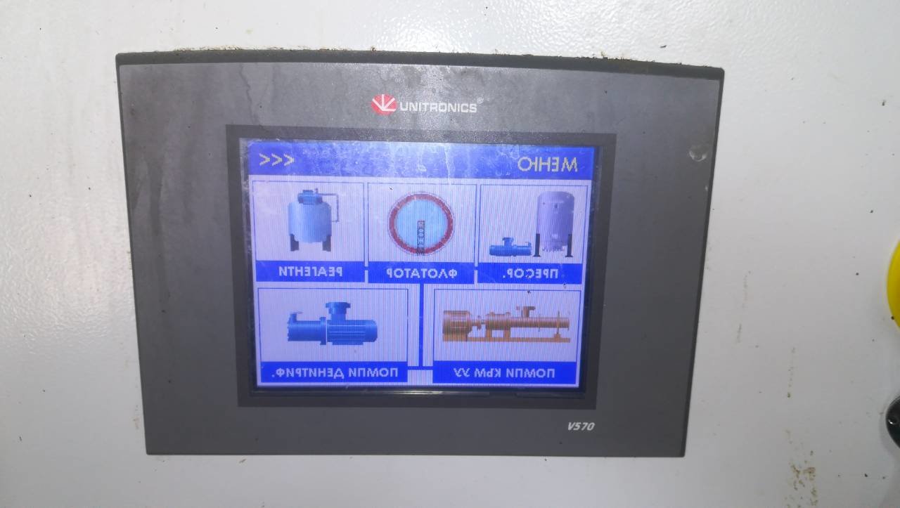
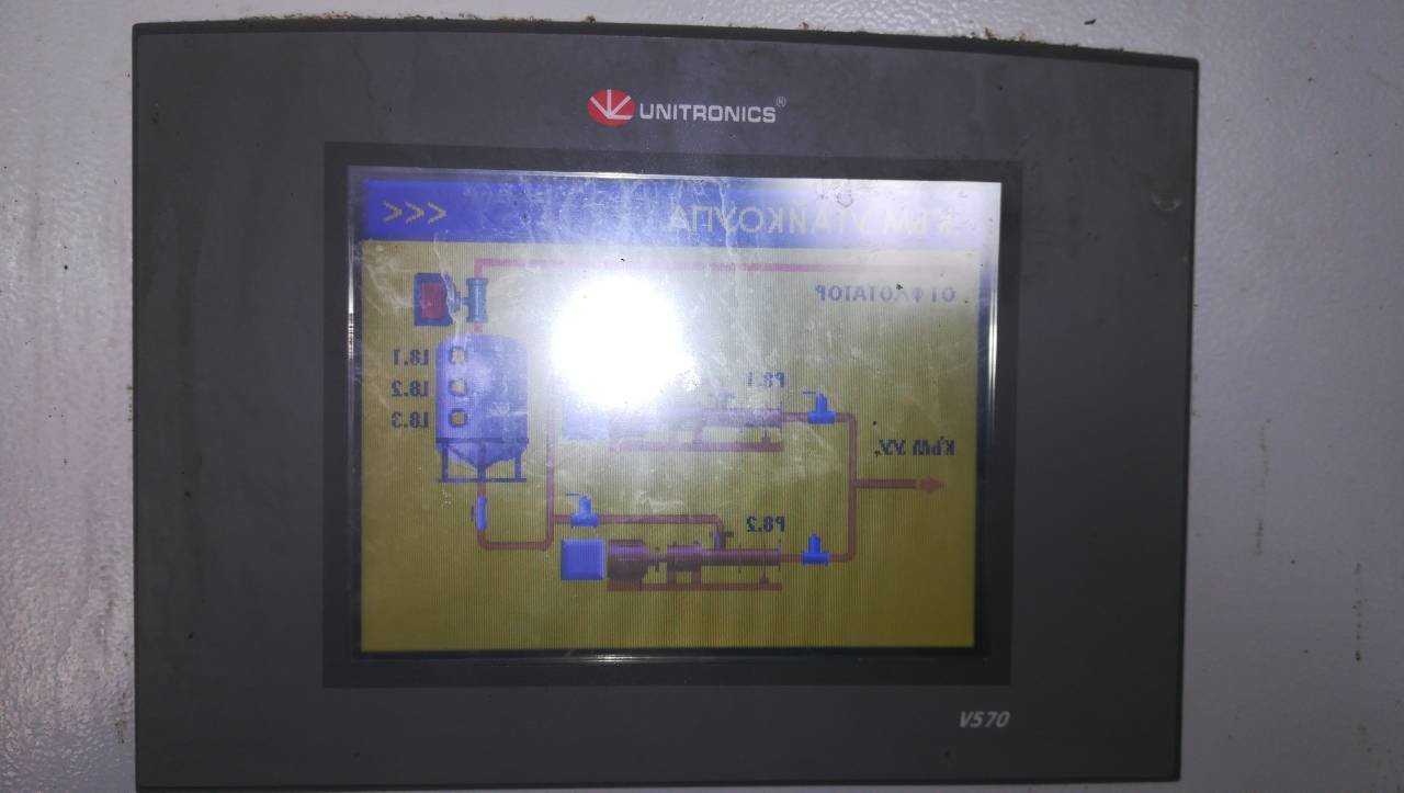
Hello, I have very strange problem with V570 display All HMI elements are mirrored without any reason Do you have any solution for this ??? Best wishes, eng. Nikola Gramatikov


-
Hello, I remove MB28 as a condition for write system log and split the nets and now everything works. Yes my data changes evey 15minutes and I write/append this raw to the sd card Why is better to use a RTC time for this. I cannot understand ?!?! Best wishes, eng. Nikola Gramatikov
-
Thank you guys. Joe's solution works for me :-)