kikitron
-
Posts
32 -
Joined
-
Last visited
kikitron's Achievements
Advanced Member (3/4)
0
Reputation
-
Program for testing encoder
kikitron replied to kikitron's topic in Vision & Samba PLC + HMI Controllers & VisiLogic Software
OK now I understand thank you for your explanation Joe. -
Program for testing encoder
kikitron replied to kikitron's topic in Vision & Samba PLC + HMI Controllers & VisiLogic Software
@Joe Tauser Thank you for the link and I dont know what did you think by homework and C programming. I dont need to test encoder directly on the machine with original panel and V430. I was just asking if it is possible to test encoder at home on the bench that I can know if its working properly. One solution is that can be tested with LED diodes on the output signals but is only visual and I think not 100% test, so i thought to use my V430 for better test. I allready connected the encoder on my V430 like you saw on the video and configure HSC input (A,B) Shaft encoder (X2) / MI 0 and link MI 0 on HMI Variable: Numeric . -
Program for testing encoder
kikitron replied to kikitron's topic in Vision & Samba PLC + HMI Controllers & VisiLogic Software
In below link I took a video with encoder that I was turning with motor in only one direction. Are the numbers on display 0->32xxx and then -32xxx to 0 normal for encoder ? -
Program for testing encoder
kikitron replied to kikitron's topic in Vision & Samba PLC + HMI Controllers & VisiLogic Software
For test I will turn encoder with motor on the bench so that is not a problem. Problem is now only in program to write for the encoder. -
Program for testing encoder
kikitron replied to kikitron's topic in Vision & Samba PLC + HMI Controllers & VisiLogic Software
Correct, real lenght is not OK at the end. I look the machine and everything is ok. Encoder is directly driven from metal sheet by the wheel. Wheel is connected with encoder with a clutch between. "Between someone changed encoder with new one (RLS RE36IA0613B10F2A00) and it was working only 1 week and then died. " How can I make a program on V430 that I can test old encoder and see that A and B channels are working ok without Z ? -
Program for testing encoder
kikitron replied to kikitron's topic in Vision & Samba PLC + HMI Controllers & VisiLogic Software
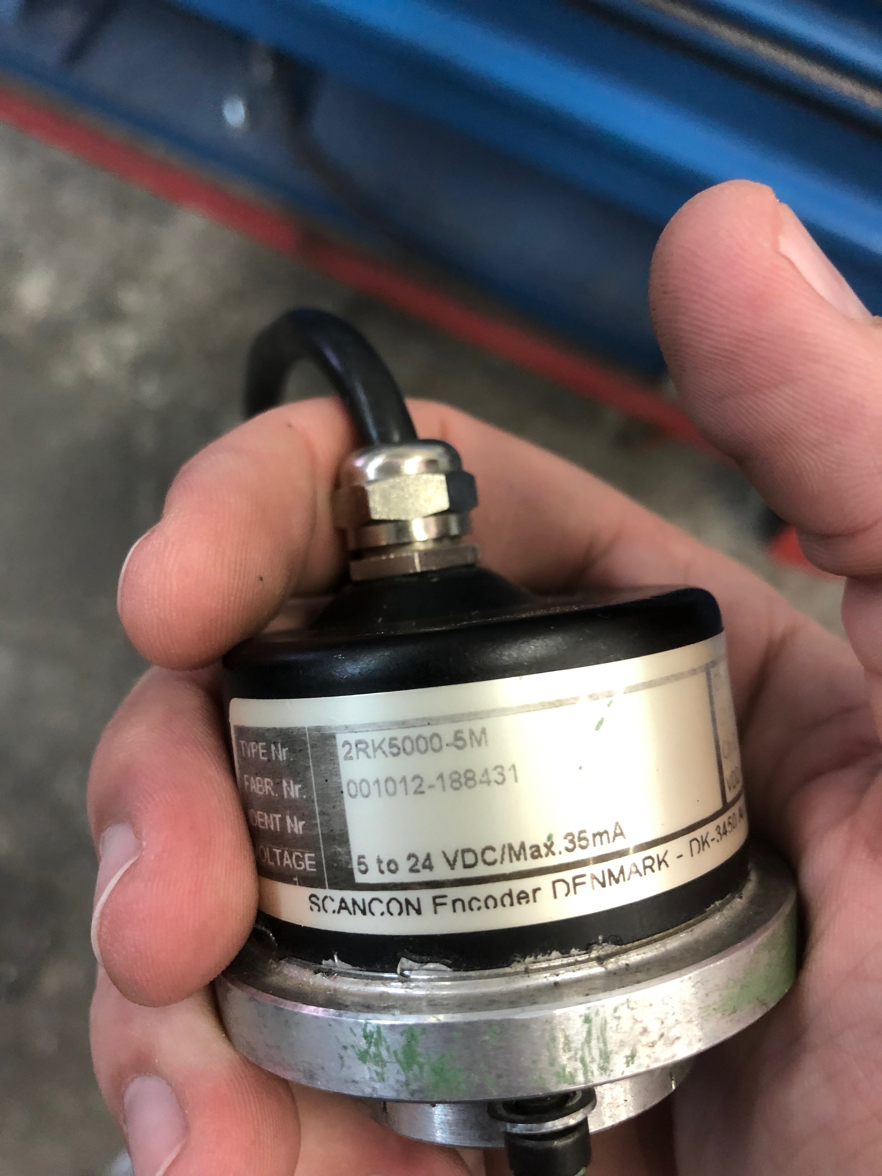
Hi to all Thank you for the answers. Encoder is 24VDC and I allready connected it on the PLC (picture in attachment). On HMI I add Variable numeric to see numbers when I turn encoder CW it goes from 0 to 32128 and then switches on -32000 to 0 and again from 0 to 32xxx. I have one machine that encoder is installed and Im not shore if the fault is in encoder so I would like to test it to be shore before I buy new one. The encoder measures the length of the sheet metal on the machine and does not show it correctly. On 6000mm of length he shows more then 500mm more, every time different. Encoder is connected on external panel that has connections A, B, +24V and GND (picture in attachment) Now I would like to write some simple program that I can see that channel A and channel B working ok. So its just for bench testing.


-
Hi, I have one encoder that I would like to test if its working ok. Encoder has 5000 pulses/turn and it has 8 wires: A, B, Z, A-, B-, Z-, +24V, GND + sheald. I connected A and B channel on my V430-J-T2 on HSC0 inputs. My question is can I do the program and test encoder properly to see if A and B channels are working ok?
-
Enter in display MIN and MAX value
kikitron replied to kikitron's topic in Jazz, M91 PLCs and U90Ladder
I found the sollution Thank you anyway, admin can delete this because I was to quick to open new topic. Regards -
Hi to all, I have one project that I read analog pressure sensor 4-20mA (0-250BAR). I need to switch valve ON and OFF on setted value min and max. Now I have setted that valve is on allways when he is below 160bar and when he reach 160bar he goes off. And when pressure drops below 150bar he is ON again till 160bar. Program is working but if I would like to change minimum and maximum values I need to set it in the program and writte it to plc. Is it possible to do changes directly on the display for MIN=0-250bar and for MAX=0-250bar? For example I would like to change MAX=180bar and MIN=100bar directly on display. test.U90
-
I have fixed resistor on potentiometer like on Picture below. I calculate it 1082 Ohm to run from 4,07mA to 19,9mA on extension module IO-AI4-AO2 (analog input). I recorder MI values: 0 = 835 5= 1390 10 = 4075

-
I tryed with different values of linearization on analog input but with no luck. I would like that when I have potentiometer in the middle on scale 5 analog output needs to be 0V. Now 0V is on scale 8. I have less rotation adjustment from 0V to 10V (scale 8 to 10). And I have more rotation adjustment from 0V to -10V (scale 8 to 0). Linearizarion is working ok only that 0V is not in the middle of the potentiometer.
-
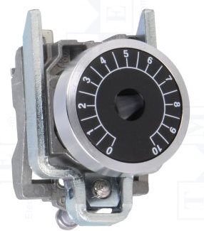
Another question about potentiometer. To regulate analog output +/- 10V Im useing potentiometer 4,7kOhm + resistor on analog input (4...20mA). Potentiometer scale is 0-10 (pic in attachment) and now I have problem that my 0V is on scale 8 and not 5. Is it possible to calibrate somehow that my 0V will be in the midle (scale 5) ? +/-10V is now working ok but my 0V is on scale 8 and I regulate 0..10V from scale 8...10 and 0V...-10V from scale 8-0.
-
Perfect thanke you for fast answer and help
-
I have another question: Is it possible to reset somehow all my MB buttons to state 0 when I turn on the PLC ? Now If I push button I got 1 and if I switch off the PLC and switch it back on I still have 1. Now I would like to reset all my MBs somehow if I forgot to turn it down to 0.
-
Thanke you @Flex727 for your help.