Search the Community
Showing results for tags 'Communication'.
-
Hi, my system : USP-104-X10 with B10 I have 3 PLC's (all same model and firmware (1.33.161)) communicating via OPC UA server with Kepware Everything is working perfectly.....until I stop my Kepware (to do some upgrading or other stuff) When I shutdown my Kepware I see following OPC-AU diagnostics differences : PLC A : PLC B: You see the difference in the current session of current subscription count -> PLC A is 0 and on PLC B it stays on 1.... When I restart my Kepware, I'm able to reconnect on PLC A, but not on B ! My Kepware gives me following error : (PLC B is GBS UNI BD1) The PLC B is actually refusing the communication The only thing is to give a cold boot on the PLC B to restart my communication... I checked (several times already 😒😒😒) all parameters (on PLC side and on KEPWARE) but all are the same... any suggestions ?


-
 Hi everyone, I'm new to the Visilogic and Unitronics environment and i'm trying to download a program on my V700 but it's only working via the serial port. I've read how to do it with the ethernet cable, it worked 2 times, then never again. This is the settings i'm working with (from what i understood we had to do) : in the V700 (named V700 in the settings): IP 192.168.1.1 Mask 255.255.255.0 GW 192.168.1.254 on socket 0 port 20256 TCP slave My ethernet driver is set to IP 192.168.1.20 Mask 255.255.255.0 GW None and when i try to communicate I set : IP 192.168.1.1 (I also tried 20 or any other value instead of the final 1 and it didn't work either) TCP 20256 V700 But the get oplc information button never returns the infos and i get the usual error message when the communication isn't occuring. Does anyone has an idea of how to solve this? Thanks
 -
 I have several PLC's running to control a building (because I can only use 8 URB adapters on 1 PLC 😒😒😒) On 1 PLC, I communicate with my lighting system (HELVARNET - DALI) to ask the status of my lights. Because it's a huge building, it takes a while for scanning all lightsgroups. For every group, I have the status in a data table. But now I want to make this data table is also available for my other PLC's (so they don't have to ask my lighting system what's the state of the lights) I've tried to update the status with MQTT, publishing and subscribing all status of all lightgroups, but this is to slowly for me..... What's the easiest way to "send" my data table to the different PLC's ? any suggestions ? my data table is built with a structure of+- 15 elements (integers, bit arrays, string,...) -> size is 13200 bytes I need something that can be run in the background, because my scantime is already high.... -> +-50000 µs (so I could have problems with my 100ms timer....)
 -
 Hello, I've recently acquired the UCR-ST-B8 router from Unitronics. The set-up was easy but it won't communicate with other devices. My goal is that the router is connected to a PLC through a direct ethernet cable and that the PLC can read the status of the router, effectivly making the router a slave of the PLC. I also want to recieve SMS messages on the router and the PLC to read those messages. *Note I did change the IP from 192.168.1.1 to 192.168.0.1 With a cable in LAN 1 of the router and the other end in a laptop we can connect to the webUI. Here (Services-->Modbus) I've configured the router as a modbusTCP slave and did save the settings. After this I close the webUI and connect to the router using QModMaster (https://sourceforge.net/projects/qmodmaster/). With this program I should be able to read the registers of the router. (I know this works as I've used it before) But when I try to read the registers it doesn't get a return signal. After this I've tried it using a PLC. But I am not really familliar with the Unilogic enviroment so I'm having a bit of trouble setting it up. As stated earlyer I want to read the data from the router and recieve SMS messages from the router and read those using the PLC. Would I need to setup the router as a router or as a modem in the Unilogic enviroment? Further if I set it up as a router would I need to take extra steps to read out the UCR-ST-B8 or should I be able to read all the data immediately? So the questions I have are: How do I read out the router? What settings need to be configured. Is it possible to read the data using a PLC? I'm using a USC-B5-T24 and how would I do that. Should I use ModbusTCP or Modbus RTU rs485?


-
 How can I use the data from 2 different plc's on the v700 by making a connection and do I need to use any additional module to display this data on the screen?
 -
 Hello to all, We are in project which requires that operator from one place, one touchscreen, controls (start-stop, change freqencies etc.) of 36 converyors. All conveyor control same VFD model Danfoss VLT 5000 (software version 3.6). We are using V1210 vision PLC with two RS485 ports. We know that VFD-s are pretty old, and we also do not have much experience with Modbus (RS485)communication. We would ask for advice, project sample, anything that can help if anyone had some experience with Modbus comunication with this type of VFD. In attachment , sample of project where we used RS 485 to control Yaskawa GA 500 VFD, can it function in same way with VLT 5000? We also cannot find adequate documentation about holding registers for this VLT 5000 VFD. Thank you in advance for every help, Best regards. V1210 to VFD VLT 500 with RS485.vlp

-
Hi all, I am newbie using Unilogic and Unistream hardware. I used to get a Samaba and worked with visiologic. So, the first question will be how Can I stablish communication via USB programming cable for the first time. Because when I put communication cable my laptop beeps, like when recognize a new device but never appears when try to download a program. This is the first time to connect my device with my computer. Despite I check usb drives and updated still not success. So, I will appreciate your help with this. Thanks, in advanced
-
 Hey all, I'm new programmer in visilogic IDE and my device is v130-33-TA24. My program purpose is to communicate via RS485, 9 bits to receive data from device. I initialized COM1 and set protocol Send&Scan by the connected device protocol. but nothing is show on screen(I've linked the received data into number on screen). I add some pictures for description. I'll be glad for help


-
Hi Everyone! I'm a beginner to the Unitronics PLCs and I currently have V570-57-T20B-J with V200-18-E1B. I have got a used one, and when powering it on, it displays old programs therefore I would like to: 1- Erase old programs to start fresh and, 2- Would appreciate with any help to get me started with linking and communicating the PLC with Visilogic. I assume the miniUSB port is only for the sake of reprogramming and not initialising the PLC with new IP address, what would be used to set an IP? Any help would be much appreciated!
-
 Hi everyone, I am using SD card explorer in order to retrieve some files from the device Advantage Pro EL Lyophilizer from SP Scientific, to do so I am connecting to the device via LAN. TCP settings, PLC name, port number are all correct and I am able to check the connection. I use Unit ID 0 (direct) But after a certain time the "listing of files" stop and the following error message « Cannot communicate with the specified UnitID » is displaying. After this happen, it is impossible to communicate anymore with the device I have to unplug the ethernet cable and plug it again to be able to communicate with it. The same with Remote access, I can communicate with it for sometime, but after about 1-2 minutes of using it the same error message is displaying. Do you have any idea how to solve this problem? Thank you
 -
 Hello to all, I am working on a new system where a Unistream B5 TR22 is a Modbus TCP master to 11 Samba PLC's Nothing to exciting but my biggest problem is a lack of knowledge. This is only my second project with a unistream PLC, with the first being a very straight forward ladder program without anything special. i do have a few years of experience with visilogic so that side is not a problem. What i already figured out is how to make the set-up on the master and slave side. the thing i don't get is addressing between the devices. In visilogic i could literally select which mb,mi,ml i wanted to read or write. Now i don't see that option. how does addressing work between these devices? At the moment i am still waiting on the unistream plc to arrive, so that i can try some stuff out, butt before it arrives i would like to make a little headway before that. kind regard's Leon Mötter
 -
 Hi all, it's my first post but I guess not least as I have a project to do using my Unitronics V1210 with CANOpen and 2 ports for Modbus RTU on board. I want to establish basic communication with my VFD (Vacon 100 / now Danfoss company) by Modbus RTU. 1. I bought RJ11 six pin plug and prepare junction so I have two cables - yellow at PIN1 and red at PIN6. 2. I connected PLC (Port 1) to VFD (A,B inputs) 3. I wrote a basic program to read the register 2101 (which is not 0 for sure) and... nothing happens. No communication. What I have checked: - Ports termination (set to RS485 with termination) - Galvanic connection between pins and end of the cable and it is ok - loopback test FB - no answer - ID, Baud Rate, Parity, Stop Bits - they are the same in drive and PLC I kindly ask if someone could check my ladder diagram as I have no idea what is wrong. KR, Bartosz
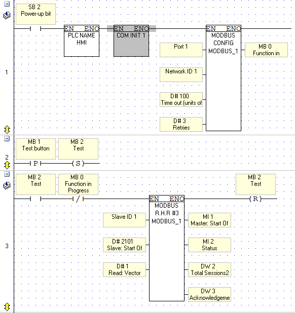


-
 Hello, I have the V700 with a Snap-In V200-18-E2B and a Inverter. I want to run a motor with a simple programs. I want the V700 communicate in RS485 with the inverter. I use a USB cable to send the program to the V700. I know i have to plug my RJ11 cables in the port of the V700 and set the communication on RS485 on the bottom of the V700. For the other part of the cable i have to take 2 of 4 wire and connect them on the Inverter. What i have to do after ? How i set the communication ? Will i have to create programs with contacts and coils to run the motor forward, or it have a compiled programs which contains some of these command ? Thanks,
 -
Hello, For a new project, I’m actually trying to establish a Profibus communication between a V350 (slave) and a Siemens PLC (Master) S7 315-2DP. V350 (Slave - Address 3) -Profibus card is installed (V100-17-PB1) -OS is up to date (comprises a Profibus card) -Connected with a Profibus cable with Siemens connectors (terminating resistance connected) -Profibus configuration block on the main routine with SB2 (power-up task) -Status message = 0 -Error message = 1 -Profibus card detected : SB178 = 1 Siemens PLC (Master - Address 2) -Configured with UniProf.gsd file -Test with only 16 Int in Read and 16 Int in Write -Test with all Bit and Int in R/W … and no communication Can you advise me something ? or maybe do you have project example or documentation.. Thanks. Best regards, Fab
-
 I have three V430-J-RH6 PLC's, they will be communicating via RS-485. Each of these plc's are running two pumps for that specific unit. My end game is to make sure that none of the units have pumps running at the same time so we don't have power issues, ex. Unit 1 is running a pump so unit 2 and unit 3 cannot run their pumps until unit 1 is finished etc. I know how to program that part in but my struggle at the moment is with how to best get that information to each PLC. I need each PLC to have constant feedback of information from each other PLC. I need each unit to know when the other units are on and off. Is a struct command the best way to do this? If not what is, and how do I implement it? I have looked into the help files on Modbus master and slave for sharing information (read holding registers, and preset holding registers) but it doesn't look like they can share MB's between plc's? I also don't quite understand how those work. Any help in this would be greatly appreciated!! Thank you! Unit 1 Governor Pump_7.31.18.vlp Unit 2 Governor Pump_7.31.18.vlp Unit 3 Governor Pump_7.31.18.vlp
 -
Hello all. I'm new programmer with Unitronics PLC. At moment trying to communicate USP-104-B10 with VFD ATV630 series by Schneider Electric, but unfortunately for me unsuccessfully. In PLC communication created Scanner and Adapter, add strucs with global tags according manual https://download.schneider-electric.com/files?p_enDocType=User+guide&p_File_Id=9346677116&p_File_Name=ATV600_EthernetIP_Modbus_TCP_Manual_EN_EAV64328_03.pdf&p_Reference=EAV64328 But I do not understand clearly what I need add in Ladder to read all needed parameters, for example, every 5 secs and how to CALL it? Maybe one of you have example of program with successful communication? I would be very appreciated. Thank you in advance for your help and reply
-
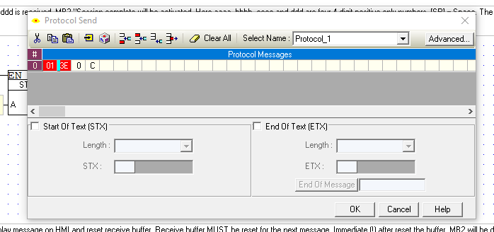
 Hi, today in our company we received an ultra filtration system that comes with a V1040 on it. We've never had worked with an unitronics system before and we are trying to communicate the plc via modbus rtu over rs485 to work with our network. We configured the com port of the plc to work with rs485 as it was factory configured to work with rs232 but we can't reach it on our system, it's just showing of offline status. In the ladders we had a special subroutine for modbus, including all the registers and status of the system, we are reaching these points but it doesn't work. I'll attach some screenshots of the COM and modbus configuration and the modbus registers that i'm trying to read and i'll appreciate any help if i'm doing something wrong. Also, if i modify the program i need to upload it all or there is an option to upload only the com configuration without stop the plc? Due to the critic status of the process i only have a few minutes to stop the plc so i'll appreciate any shortcut to work faster on the system. As i said we've never worked with this plc before so we don't know the kind of responses of the system.


-
 Hi All! I am new to actual PLC programming and ladder logic but I have been working with Yaskawa drives for 11 years and am quite proficient on that end. I have a V1210 and have found it fairly easy to work with aside from visilogic crashing quite often on windows 10. I really want to start interfacing VFD's via modbus rs485 and I am looking for a place to start. Are their any example programs or tutorials specific to the V1000 that could help me get a start? I did see another topic similar to this, but the links the support staff listed were broken. Thanks in advance! Kyle
 -
 Hello! I'm trying to configure CanOpen communication between Lenze ECSxP Posi&Shaft and Unitronics V1210. I want to set the velocity and the position using PDO1. If I give a high level to the fifteenth bit the control word becomes: First 15 bits are control bits (begin from 0) The velocity value is between 16 to 31 bits it means i can store the value using MI. The velocity is effected in the process data telegram in percent of maximum speed. And the position is between 32 to 61 bits. It is carried out in the process data telegram in resolver increments. I want to give values between 16 and 61 bits It is not possible to use MI to store the position value i need DW, however...inside CANopen Configuration block for RPDO Tx i can use only MI only ML or only DW. Could you give me suggestions how to solve the problem?
-
 i so far finished my ladder programming in unitronics V1040 plc and created a webpage to use in raspberry pi to view the same HMI screen in my webpage at the same time whatever output i get from the Plc HMI. now i hv the problem is, how can i communicate plc and raspberry pi.can i connect the i/o and o/p of both plc and raspberry pi . is any coding ive to write in the raspberry pi terminal for the communicate with plc. please advice me.
 -
 Hi, I have Unitronics PLC V130-J-TR20 PLC, which is a master, and two Jazz JZ20-J-T40, which are slaves. I need two of the slave Jazz PLC's to communicate with master V130 PLC. I have made configuration in PLC Program for read and write, but it's not working properly. When i set bit for request to read PLC3 (MB100), it reads it normally. But, when i try to read PLC2, it reads same value that I have on PLC3, although Communication is OK with PLC2. I have read example project, and used it to configure communication between PLC's, like you can see in the images. Regardless of what I do, one of the PLC's is not working properly, communication says it's OK, but keeps reading values from other PLC. IP addresses are different, of course, and i have typed them correctly into the MODBUS IP Configuration, like in the image. On my Jazz PLC's I have done everything like Example project in U90 Ladder says. Is there a way of fixing this? Thankful Nikola Ljubinkovic
 -
Hi, I'm using Unitronics PLC JZ20-J-T40, and ZView SCADA. I have successfully downloaded my program into PLC, and tested communication via usb (Serial), and via Ethernet (MJ20-ET1). It's all working properly. Problem begins when i try to connect my PLC to scada PC. With USB everything is working normally, but it's not an option for me to work with usb connection. I want to work with Ethernet communication between PLC and SCADA. What should i do to make it work? Regards Nikola Ljubinkovic
-
 I am getting the following error when trying to initialize/go online for the first time with my V570. ----------------------------------------------------------------------- "Communication over TCP/IP could not be established due to one of the following reasons: - cable connections are not secure - incorrect TCP/IP settings (IP address, Protocol type, Port number) - the connection is currently being used by another application. " ----------------------------------------------------------------------- Right now the first net in my main routine is checking SB2, following by Set PLC Name, followed by a TCP/IP - Card Init, (setting IP to 192.168.1.10), and then a Socket Init (using socket 1, TCP, port 20256, and client set to server [slave]). In communication and OS I have tried my connection as both TCP/IP (Call) & TCP/IP (Listen), I am using a favorite with the same name and IP as specified above. My local machine IP is set to 192.168.1.253. I am connected directly to the ethernet port on the V570 with the V200-19-ET2 ethernet com port I am trying to "stop-download-reset" to go online and I get the above error consistently. I'm sure this is a basic question but I have watched all the tutorial videos and read the help files and I believe I am doing everything I am supposed to, any advice would be great!
 -
Hey guys, I have a UniStream 7" PLC connected with EX-RC1 expansion module via CANBUS. The CANBUS is connected according to the info in the datasheet with 120 ohm resistors and everything. The complete configuration that the PLC communicates with from left to right is as follows: EX-RC1, 3 x IO_D16A3_RO16, 2 x IO_ATC8/AI8, IO_D16_A3_RO16. The PLC and the EX-RC1 is grounded and connected as it should. EX-RC1 is programmed (initialized UniCAN) and the LEDS are all working propperly (PWR ON, I/O COMM ON, BUS COMM ON). Accordingly I am able to read/write all the inputs/outputs. So, the whole system and configuration is working propperly. A few (2-3) months later EX-RC1 dies (only PWR LED is ON). I can't read/write any of the inputs/outputs and the IO modules I mentioned earlier all blink ( no communication established). I tried restarting the whole configuration by turning the power supply OFF and then ON. Tried to reprogram the EX-RC1 but when the download starts it shows an error that the device is not available (not sure what the error said). So I thought to myself what the heck. It died, it happens and I replaced the module with a brand new one and installed a separate power supply used only for the EX-RC1. The whole configuration started working again, the comm was up and the PLC software was fully functional (able to read/write and execute). However a few months later ... surprise ... EX-RC1 dies again. The exact same circumstances. Is this a compatibility issue or? Thanks in advance for your help. Any suggestions/ideas are really appreciated.
-
 I'm trying to configure CANopen communication for a first time. NMT Status integer consists four values: 00, 7F, 05, 04. However when i press "Online test" the value is 517 (dec)?!?! - 205 (Hex). Please tell mi what it means, where is the mistake and how to fix it?


