Search the Community
Showing results for tags 'modbus rtu'.
Found 13 results
-
 I have a US5-B10-RA28 with a UAC-CX-01RS4 card fitted onto the back. I have 2 sensors needing to be wired to fit the PLC Program, however the 2 sensors have a different default parity value, meaning they don't work together and only work when I set the 01RS4 card in unilogic program to either Parity = None for one sensor and Parity = Even for the other sensor. This however is not suitable for my application as I constantly have to redownload the project to the PLC changing the parity value for the module to get one sensor running. So my question/ help needed is how can I change the Parity value of the sensor below, and is there a way of doing this through unilogic? Thanks Soil Moisture & Temperature Sensor User Manual-S-Soil MT-02.pdf
 -
 Hi all, it's my first post but I guess not least as I have a project to do using my Unitronics V1210 with CANOpen and 2 ports for Modbus RTU on board. I want to establish basic communication with my VFD (Vacon 100 / now Danfoss company) by Modbus RTU. 1. I bought RJ11 six pin plug and prepare junction so I have two cables - yellow at PIN1 and red at PIN6. 2. I connected PLC (Port 1) to VFD (A,B inputs) 3. I wrote a basic program to read the register 2101 (which is not 0 for sure) and... nothing happens. No communication. What I have checked: - Ports termination (set to RS485 with termination) - Galvanic connection between pins and end of the cable and it is ok - loopback test FB - no answer - ID, Baud Rate, Parity, Stop Bits - they are the same in drive and PLC I kindly ask if someone could check my ladder diagram as I have no idea what is wrong. KR, Bartosz
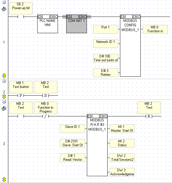


-
 Hi, For personal use I'm using a V280-18-B20B with a V200-18-E1B. snap-in module. In order to register temperatures, I'm going to use a (third party) Pt100 I/O-module which communicates via MODBUS RTU. According to the documentation I would have to configure comm. port 2 of the V280, through jumper settings, for RS485 communication. And, again according the documentation, these jumpers must be present on the circuit board directly behind comm. port 1 and port 2. But unfortunately in my case there are no jumpers on my V280 to set comm. port 2 to RS485. Several questions popping up in my mind: Are there V280 models which don't have these jumpers to set comm. port 2 to RS485? Is the documentation incorrect and do I have to look better (and on a different place) on the circuit board? To communicate through RS485 with the V280, do I have to purchase the V200-19-RS4 Snap-in module (RS485 comm. board), because comm. port 2 is just not configurable for RS485 on the V280 (which I actually expect, because the name at port 2 only indicates RS232. If port2 is also configurable for RS485, you would expect port2 to be labeled RS232/RS485). In advance, thank you for your response. L.
.thumb.jpg.52091e18fa25dcaf50f38a9f8128b527.jpg)
.thumb.jpg.7a5d06fd0f3bcff161ea8d9a274c9f4d.jpg)

-
Hi. We installed 3 x V570 plc's running on ethernet network. Also connected Indusoft scada system to system. Delta vsd run also on same network. All working fine and then sometimes comms to scada stops. Also comms to VSD's not constant. If comms to scada laptop fails we have to restart plc's to get comms again. Any suggestions or help will be appreciated
-
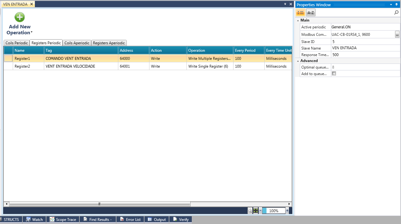
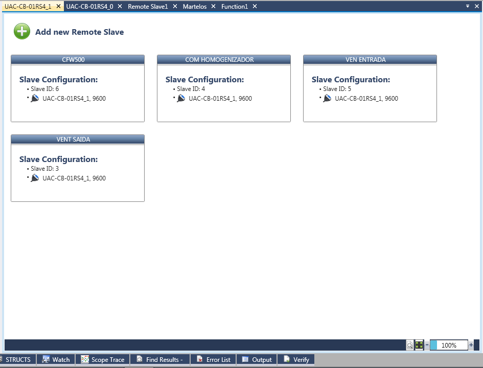
Hello friends. I am using a USC B5 TA30. This PLC is communicating with 4 frequency inverters in RS485. I managed to establish communication but it is very unstable, the problems are as follows: -It does not update in real time, it takes a few seconds because I need to be updating the routine call manually; -All the inverters are configured correctly and work individually just by changing the cable between them, but when I connect them all there is no command of two or more (each with their own address); Some data that may be relevant: -All equipment is functional; -They are Toshiba inverters of the VSF15 and VF-FS1 lines; -The distance between the components is small and I'm working with 9600 Baud Rate, Parity None, Stop Bits 8; I think the problem is in some configuration in the call of routines related to time or ModBus configuration of the UAC-CB-01RS4 cards, the RX / TX LEDs are blinking and very fast as usual in OK communication. I already have an HMI in the same communication working on the other UAC-CB-01RS4 card, it also has a little bit of instability, but it reads and writes the data on the PLC. can anybody help me? Thank you very much and I wish you well!


-
 Hello, I have a school project where i was tasked to read an MI from a Slave PLC as a Master PLC. I've tried using the help fuction, but i havent seemed to make it work. Thanks in advance
 -
 Hello my friends, I have some difficulties communicating with a power meter, it has a Floating Point 32 address, and I can't communicate. I performed tests on KepServer and got success and also with ModbusScan. You could be helping me set up the program or teach me some procedure you might be doing to establish communication. Attached is the list of registers.
-
 Hi there, this is my first time working with unitronix plc and I have some problems with understeanding how does modbus communication works. I am using visilogic 1210 plc and I want to read some parameters from Iskra FPC400. I want to use modbus because FPC400 only supports rs485 communication. First I did set up com port and configured modbus. (As you can see from pictures that I included) I want to read 27 parameters from FPC400 (As you can see from picture that I included, I want to read 27 parameters from adress 4112 - 4139 ) and store them in 27 different variables in my plc. (MI4000 - MI4027) As I understood, I need to set start of vector for reading variables as 4112 and length needs to be 27, and start of vector on my plc is 4000. Does this means that program will read 27 parameters and store them into my plc starting from MI 4000 to MI4027?

-
I need to establish communication betwwen jazz (master) and energy analyzer-klea as slave using RS-485. Model of jazz is JZ10-11-UA24 with MJ20-RS. I need to read float value in klea starting addres 0 (Average voltage of three phases) I am newbie with unitronics and modbus ... Tnx in advance for any help. In attached files are: 1-klea modbus function 2-data adress in klea 3-example in klea


-
 Hi, I'm writing an application involving 1 master and 9 slave controllers - all Unitronics. The master PLC is a V1210. One of the slaves is also a V1210. The remaining 8 slaves are V130s. All i'm trying to do is sequentially read 1 coil from each of the slave PLCs. I know that this should be ridiculously easy... ...However, I'm finding that the "Function in Progress" bit gets stuck on after the master only attempting to read from 2 of the slaves. I've tried using timers of 100ms - probably excessive - after each Modbus Read Coils function block. Also, just to mention, I don't have all 9 slave controllers with me for testing - I've got 2. Is Modbus good at handling when it can't get thru to a particular node and just moving on to attempt the next one? Any help much appreciated, James
 -
Hello Can you give me an advice how to solve the problem.Well,I have PLC Jazz 20 R31 connected to modem(Scada) by RS485(Modbus protocol). Everything works but from time to time the communication between the devices disappears and I have to reset the PLC If I wanna restore the communication. It happens often when some unit(pumps) is switched on. The file with my Modbus config is attached How to solve the problem? Sincerely Wladimir unitronics.U90
-
 Am using Red Lion display, model PAX2D, with an option card for RS232, and want use Modbus RTU to display values from a V350. I can get successful comm. by connecting RXD from display to RXD(pin 3) on V350, and TXD to TXD(pin 4) with no ground. As soon as common (pins 2 or 5 on V350) are connected to RS232 common on display, comm. halts. By wiring as above, I can read values from registers in the display, but they seem to be random numbers, not anywhere close to what they should be. For instance when reading register 40483(display baud rate), a value of 8960 is returned no matter what the baud rate is actually set at, and I would be expecting to see a number from 0 to 5 for the 5 baud rates available on the display. PAX2D display manual: http://www.redlion.net/Products/Groups/Counter/Rate/PAX2D/Docs/04038.pdf PAX2D Modbus table: http://www.redlion.net/Products/Groups/Counter/Rate/PAX2D/Docs/04045.pdf PAX2D RS232 option card manual: http://www.redlion.net/Products/Groups/PAXOptionCards/PAXCDC1,2/Docs/12018.pdf V350 program: https://www.dropbox.com/s/86hmdjtqg0qdkqd/Test%20Display.vlp I talked with Red Lion tech support to make sure display setup is correct. Appreciate any help!
 -
Hi all, Im having a new application in which i want to fetch data from 5 - V130 Plcs and store into a database(MS access). Im planning to poll plc data by c# code. for just a serial interface i can get the data from the plc. But how can i call each unitID? Is there any examples for modbus c# codes. send me someguidelines. Thanks in advance, Jerin....


.jpg.4345d26ea257025e1d7180d27f7f5aa8.jpg)
.jpg.81fbe091dc5dc71558cb66c0736de9ea.jpg)