Sremac
-
Posts
23 -
Joined
-
Last visited
Content Type
Profiles
Forums
Gallery
Events
Blogs
Downloads
Articles
Media Demo
Everything posted by Sremac
-

EXF-RC15
Sremac replied to Nikolay Kovalev's topic in Vision & Samba PLC + HMI Controllers & VisiLogic Software
Thanks a lot for your effort. I also tried (build all), also without errors. But The Creator remains silent... Such a big mystery that EXF module... -
EXF-RC15
Sremac replied to Nikolay Kovalev's topic in Vision & Samba PLC + HMI Controllers & VisiLogic Software
Thanks Joe, sure I will test it as soon as it arrives. But my question about PLC power (speed) and interrupts are separated from CAN communication. As I understand, EXF-RC15 actually can be programmed to perform as a standalone PLC, I can connect counters and encoders and put some ladder logic based on inputs and outputs normally. For instance, it shold be possible to issue a command for make a preprogrammed number of pulses movement by triggering one input. Or dose something with a dosing screw (encoder as a Reload HSC). Then, it would be nice to have interrupt option to stop the movement by hardware interrupt and immediate output refreshing. Then I can connect this unit to a main PLC by UniCAN to set the number of pulses, or to trigger the preprogrammed execution instead of triggering the EXF_RC15 input. But the accuracy of moving or dosing would not depend on a PLC cycle or communication speed, because it is controlled by HW interrupt, OK? So, finally, does EXF-RC15 support interrupts or not? -
EXF-RC15
Sremac replied to Nikolay Kovalev's topic in Vision & Samba PLC + HMI Controllers & VisiLogic Software
Thanks Aus, in this case CAN cable is about 1 meter long, so communication speed would not be the problem. Still remain the items 1) & 2), interrupts available or not on EXF-RC15? It would be also nice to know what kind of PLC you deal with while programming EXF-RC15, i.e. speed of processing 1K ladder for instance... -
EXF-RC15
Sremac replied to Nikolay Kovalev's topic in Vision & Samba PLC + HMI Controllers & VisiLogic Software
Hey Joe, I just need two additional encoders in my application (V700+V200-18-E4XB). I decided to go with EXF-RC15. I also studied example programs, they are mainly about communication. I understood that EXF-RC15 is actually a PLC communicating with the main PLC by UniCAN. I could not find any information about it's speed and functionality as a PLC. 1) Can I use _Interrupt HSC x,y routines for HSC, just like with V700? 2) Also _Interrupt 2.5 mS ? Or maybe _Interrupt 1.25 mS ? 3) UniCAN is fast. But I need to know what would be the the time frame (cycle time) for continuously sending and receiving say 20 MIs between EXF-RC15 and V700. Many thanks in advance! -
Small update: I used Version Swapper a lot of times with various Visilogic versions without any problem since!
-
Dear Ausman, thanks a lot, I've tried your method with partial success. Also it's too complicated, I mean too error prone for an old guy like me... One new moment concerning W10 and Version Swapper: After fresh W10 installation I've had the same issue as described above, Run-time error 339, amiTapi .ocx components not registered/missing. I tried to locate the file amiTapi.ocx on my computer without success. But on the other laptop I've found it, made a copy to the USB flash and transfered it to c:\windows\system32 folder. Note 32-bit W10 version, otherwise on a 64-bit version it should be copied on a C:\Windows\SysWOW64 folder. After that I found regsvr32.exe in the same folder. Then I started command prompt (cmd.exe) as an administrator, and typed: cd c:\windows\system32\ regsvr32 amiTapi.ocx /s This was actually the registration of a copied file. Then I tried to register Visilogic Swapper version with Version Swapper , and get the same message but this time Actbar2.ocx was the problem. I repeated the procedure, exactly the same as for amiTapi.ocx file, and now I have no problem with Version Swapper, it normally works with all Swapper Visislogic versions, downloaded from Unitronics site. Once again, for W10 64-bit version users, just instead of C:\Windows\system32 folder use C:\Windows\SysWOW64 folder. And thats it. The onlz problem is that one can not be able to find the missing files. They are extremely vulnerable and should be used only if they originate from original Windows installation (usually Resource folder).
-
Looking forward to hear from them. Greetings to all!
-
So, what now? Please don't tell me to roll back to Win7 or, even worse, to use virtual machine...
-
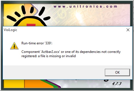
Joe, I suppose you're right about Microft world and stuff... Unfortunately, even if I explicitly run Swapper as administrator and upon registration of say VisiLogic V4.7.3. I explicitly run VisiLogic.exe in .../VisiLogic_V4.7.3./Main/ folder "as administrator" it still says: "Run-time error 339" - snapshot attached.
-
No matter I run the application under administrator's account on my laptops with Windows 10 (both 32 and 64-bit versions), Version swapper would not function normally unless I specify "Run as Administrator" option as I start the program. Yes, it is possible to specify this option on a shortcut that starts Version Swapper, so it always runs "as administrator". But, still there is a big problem: even than some older versions would not run after being registered with Version Swapper, there are various error messages that says that some componenets could not be registered, that are missing or invalid. It works normally for some latest versions, I tried 9.5.0 and 9.8.22 lately. I normally connect remotely with my customer's PLC's and I need to use exactly the same VisiLogic version in order to verify the program in a proper way before making any changes eventually, so it is actually a big problem to me. Also, I tried to install the whole package in a folder other than Program Files (X32 or not, depending on Windows), and to change its security properties - everybody has full access rights, but still the same situation. Any thoughts?
-
Very odd situation, for the first time in a decade using VisiLogic: Yesterday, after I finished my current project I burned "Upload Project" to the V570 and saved the file. My normal procedure is to make file backup, so I instantly used "Save as" within the same folder with _bak added to the project name. After that I performed verification with the OPLC, which returned all the check marks as usual. Furthermore, my normal routine includes synronising "Documents" folder with the one on a USB memory stick, which I also performed imediatelly. This morning i needed to change some small detail in a program, so I normally performed verification before making any changes to a program, imediatelly upon making a connection to the OPLC, and it failed! Instead of check marks I've got a red crosses next to "Download DLU's" and "Project upload file" fields . I also tried to verify other 3 backup files (one from the computer and other two from USB memory stick and all the time I get the same result. At the moment I am very concerned about that. Hundreds of time I preformed the same routine without any problem, and now this! OK, I decided that it is not possible that all four copies of the same project file are corrupted, so I decided to discard the OPLC content and burn the project again and see what i am going to get with that. But before doing so, I tried to upload the project from the OPLC to a new project. Upon finishing the upload the verification again failed the same way as before! It says the the uploaded project is not the same as himself! Is it possible that really the project image file was corrupted withing the PLC flash memory? After I made necessary changes, I burnt the project again to the V570 and performed the same backup routine as described. All the verification passed, but we'll see what is going to happen tomorrow... I use latest VisiLogic 9.8.18 with up-to-date operating system files on a Win10 machine. What happened?

-
Swapper Versions
Sremac replied to FireNeck's topic in Vision & Samba PLC + HMI Controllers & VisiLogic Software
Dear Eyal, thank you very much for that, a am going to try it ASAP. I always wait for Swapper version of my current VisiLogic before I switch to newest version... -
Swapper Versions
Sremac replied to FireNeck's topic in Vision & Samba PLC + HMI Controllers & VisiLogic Software
Can somebody explain how to register previous version with the swapper, please? BTW, when can we expect V9.5.0 Swapper? -
EX-A2X Communication Problem
Sremac replied to Dave's topic in Vision & Samba PLC + HMI Controllers & VisiLogic Software
It seems that there is a mystery about exact functioning of a "secret" SB90 system bit... Reading this topic I am seriously concerned about a lot applications I've made without thinking of such a problem. I suppose that I just expected that the system itself was to recognize that something is missing from Harware Configuration and safely stop everything in such a situation. Now I am not sure how my system would behave... I strongly support the request of providing meaningfull way to control system behaviour in the situations when there is a problem with any expansions, Snap-in, wired, wireless... Why not clearly giving the programmer the way to control it and to decide what would be the best to do if... Suppose that the OPLC always check the presence of everything configured in the HW (a watchdog funcion) and by default stops and turns everything off if the watchdog chain is broken, sets some SBs to show the programmer exactly what's going on, but let him reconfigure the behaviour in such a situation i.e. enable/disble some parts of a watchdog chain and probably write emergency subroutines that would be triggered and executed under such a condition. Nice, isn't it? And safe too. -
AO6X 4-20mA problem
Sremac replied to Sremac's topic in Vision & Samba PLC + HMI Controllers & VisiLogic Software
Dear Nacho, thanks a lot for the remark you've made, somehow I missed it while reading the Guide. On the other hand, this means that the unit actually produces 0-20mA in both modes, so one has to use linearization network (or some similar calculation method) to scale 0-OUTmax in 819-4095 units instead of 0-4095. Logical question is then why there is a switch in a Hardware Configuration menu, i.e. what really changes when I change it? It seems - nothing. Also, I don't expect output current to be dependent of the inverter input impedance as long as it is within specified range. -
It is the second time I have the same problem with AO6X analog output modules - although in the Hardware Configuration I choose 4-20mA option for the current outputs, they produce 0-20mA anyway! Norlmally I use it with an inverters set to 4-20mA frequncy reference. OK, I switched inverters to 0-20mA, but there's another issue - 20mA does not correspond with the value of 4095 in an assigned MI, but with 4080! Very odd behaviour, not a real problem to me becuse I made it work anyway, but I had to report it here. My best regards to all!


-
Reset Problem--urgent!
Sremac replied to Sremac's topic in Vision & Samba PLC + HMI Controllers & VisiLogic Software
Dear Ofir, thanks a lot for zour reply. I am sorry for my late response, but as soon as I posted I myself found out the workaround. But, there is an issue about it: since calculation is provided only once per OPLC cycle and there is no possibility to use interrupt subroutine, is this really a HSC? The only thing that you get by using it is that you don't miss a pulse shorter than a OPLC cycle time. Anyway, my application could "swallow" it, so now everything work as expected. Also, I suggest that there should be a short notice about that limitation in the hardware manual, so nobody gets as confused as I was. Thanks once again. -
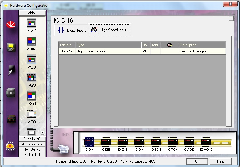
Well, i consider myself experienced user on Vision PLCs. Now I am facing a problem that is blowing my mind! i use maximum loaded V570 configuration (Snap-in, 4 x DI16, 2 x TO16 and 2 x AO6X with EX-A2X adapter). I already use incremental encoder on my Snap-in module (A, B and Z pulse) emulating absolute encoder. But i need two more counts in order to determine some sync points on the other moving parts on my cartoning machine. So I connected just phase A of an incremental encoder to expansion DI16 module and in HW configuration make it work like a HSC. It counts up all right. But it doesn't let me reset MI1 connected to it no matter what I do. I tried to use Reset numeric, storing #0 to MI1, multiplying it by zero... Even in on-line mode it won't send #0 to MI1! Then I tried to trigger physically (with 24V, PNP configuration) Hardware input #46 designated as the Reset input for a HSC that uses input #47 as the HSC (and counts!) - still nothing. I absolutely need to reset MI1 before I make a move that will produce counts on every machine cycle! Any help, please?

-
Ressetting HSCs
Sremac replied to 2rlp's topic in Vision & Samba PLC + HMI Controllers & VisiLogic Software
Well, i consider myself experienced user on Vision PLCs. Now I am facing a problem that is blowing my mind! i use maximum loaded V570 configuration (Snap-in, 4 x DI16, 2 x TO16 and 2 x AO6X with EX-A2X adapter). I already use incremental encoder on my Snap-in module (A, B and Z pulse) emulating absolute encoder. But i need two more counts in order to determine some sync points on the other moving parts on my cartoning machine. So I connected just phase A of an incremental encoder to expansion DI16 module and in HW configuration make it work like a HSC. It counts up all right. But it doesn't let me reset MI1 connected to it no matter what I do. I tried to use Reset numeric, storing #0 to MI1, even in on-line mode it won't send 0 to MI1! Then I tried to trigger physically (with 24V, PNP configuration) Hardware input #46 designated as the Reset input for a HSC that uses input #47 as the HSC (and counts!) - still nothing. I absolutely need to reset MI1 before I make a move that will produce counts on every machine cycle! Any help, please? -
PWM FB problem
Sremac replied to Sremac's topic in Vision & Samba PLC + HMI Controllers & VisiLogic Software
Hay everybody! I am still waiting for the confirmation that the problem is solved. Tired of workarounds... -
PWM FB problem
Sremac replied to Sremac's topic in Vision & Samba PLC + HMI Controllers & VisiLogic Software
Any news? -
For some time I get complaints from my customers that my PID controlled heater loops overshoot a lot at the beginning of the operation, and then functions OK. Talking about V570. PID is connected to a physical output driving SSR thru a PWM FB. At the begining of the heating cycle PID Control Value is 100% and PWM output bit is permanently ON, of course. But later on, as the temperature rises, CV naturally starts to fall (99%, 98%, ..., 57%, ...) but PWM output bit is still permanently holding ON state, without any blinking, so my SSR is fully open, providing 100% average power to the hater, overshooting the setpoint a lot. Then, when CV becomes 0, output bit is finnaly reset, and from that moment everything is working fine - the temperature is falling, CV is rising, PWM is producing modulated pulses and the temperature is finaly under control. Also, I searched for something else that could keep output bit clamped to ON - absolutely nothing, because it occurs only two times in my program - in PWM block, and in a plain different net, driving the physical output. Also, PWM scan FB is placed in the Main Routine, so it executes all the time. This is why I added a few ladder nets that are forcing CV to zero for 0.1 second every 10 seconds during initial heating of the system, and that solves the problem, i.e. PWM output bit is pulsing immediately after CV decreases below 100%, so the regulation is fine all the time, without noticable overshoot. The question is why such a strange behaviour? (Of course, I use VisiLogic 9.3.0 with the latest OS 3.4.0)
-
Visilogic Version
Sremac replied to Damian's topic in Vision & Samba PLC + HMI Controllers & VisiLogic Software
I understand and appreciate Unitronics concept as constantly developing and upgrading. So every user is strongly advised to update VisiLogic regularly (as well as the OS), and to use Version Swapper for being able to fully interface with the applications created with some of the previous VisiLogic versions. Understood in this way, it seems quite natural always naming the latest version "current". Once you get used to it, it makes no problem at all.