

Isakovic
-
Posts
192 -
Joined
-
Last visited
-
Days Won
13
Content Type
Profiles
Forums
Gallery
Events
Blogs
Downloads
Articles
Media Demo
Posts posted by Isakovic
-
-
As Flex said you should look at examples and mimic the form.
From my experiance Modbus runs fine without delay, both TCP and RTU. In Net 1 you can add NC contact for "Modbus busy" bit after MB35 and reset MB35 at the end of net. And do the same for Net 2.

-
Controller itself has no problems, picture was taken out of curiosity during an inspection.
7 minutes ago, Flex727 said:I like to have a screen on most of my projects that includes PLC temperature, scan time, and other misc info that could be useful for troubleshooting.
I never used system memory for temperature measurement. What is a typical temperature that you get on PLCs?
-
It was E76, not sure about lens angle.
-
Hello everyone,
I would like to share this thermal image I got, if anyone is interested. It's a V700 with V200 connected on the back of it.
Outside temperature was around 20°C, cabinet could be better ventilated.

-
 1
1
-
-
On 3/6/2022 at 7:24 PM, Flex727 said:
Maybe use a Data Table with several string columns, then read out the Data Table line into a vector of MIs?
I do something similar with "List of Texts" fields. After every action controller does it writes a new line on top, old ones move one step down. This screen is usually called Status Terminal or something similar.
On 3/8/2022 at 10:44 AM, AlexUT said:Is it worth the time and money?
It my case no. It also doesn't help much with troubleshooting, but it looks good so I usually do it, especially on bigger screens.
-
20 hours ago, Ausman said:
I haven't looked at the vlp, but my thinking is that the whole point of transitions is changing state from one scan to the next. All the help info refers to "scans"...which I read as complete scans.
Yes help doesn't go into much depth. I did some more tests. Just out of curiosity, can't really say I know stuff if I'm not sure about fundamentals.
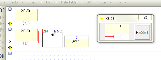
This program works as expected, both in main and in routine. It sets it on odd, resets on even scan number. Computer works.

Next program doesn't recognize transition. It is in a subroutine called from transition contact for F1 button. I would manually reset XB23 after setting it with F1 button. It does recognize normal contact.

Next program is the same (should behave the same) in main and it does recognize transition as well as normal contact. XB23 is again resetted manually.

I guess when using transition subroutines should be taken into account. Subroutine has to "see" bit change for transition to work inside of it. Am I right here? But also shouldn't transition be updated as soon as change happens not at the end of scan.
Next two programs recognize transition in the middle of execution.


Sorry for the curtain of pictures. As Aus said it's unlikely to run into these issues when doing normal, standard, nonexotic programs. But it would be great if someone who knows this stuff under the hood could explain it.
-
Ok, I recreated the problem in V430.
- Set XB23 in first scan (I held F1 pressed and clicked once "Single Cycle"), reset in second scan (I held F2 and clicked once "Single Cycle" ) and it works normally. Wait one idle scan then repeat and it works normally again. If you don't wait one idle scan and set XB23 in third scan program doesn't recognize transition contact. If you use normal NO contact program works fine again.
I can't explain this, I wish someone with more in depth knowledge of Visions could tells us how transition works behind the scenes. I guess lesson here is that transition contacts shouldn't be used when bits they reflect are changed from scan to scan.
-
Can't say much from your program. It seems when you press #8 on keypad your program increments MI18 to value 3 (net 1 to net 4). When you press #9 on keypad MI18 is incremented to 4 and XB23 resets.
On 2/4/2022 at 6:27 PM, Sideway said:However, if i go through my routine, reset my XB23 at the end of it, then i wait 1 scan cycle, then retry my routine, it works properly.
You mean reset it manually? I'm not sure what is the exact problem. One scan cycle lag shouldn't be a problem for control by pressing buttons.
If this is a question about inner workings of transition contacts, if they can change state during the scan cycle or are only updated once per scan, I would also like to know.
-
On 1/9/2022 at 5:49 PM, Flex727 said:
And, finally, remember that if you are going to use any image in "Transparent" mode, that the transparency is controlled by the single pixel in the top left corner of the image. Make sure that pixel color is unique to everything except the background. I usually use pink so that it stands out to me while editing (the pink will disappear on the PLC HMI screen).
I didn't know this about top left pixel. Learned something today.
-
I believe @steliosliv refers to -P- contact inside of function. In that case you should make a bit for that positive edge and have a network like this in main before function is called several times:

Then you use normal contact of that new bit instead of -P- contact inside of function.
-
-
Never had such a request, so I did it as an exercise. As suggested in topic @kratmel posted when dealing with time intervals it's best to use RTC to UTC functions, so you manipulate only with one DW variable. That's also my experience.
-
 1
1
-
-
On 9/3/2021 at 10:51 PM, VFU1076 said:
It works fine with a V700 as it gets an Ethernet port, but It's been difficult to get it running on a V570.
You can also get an Ethernet Card for V570.
-
Did you use MI3 and MI26 anywhere else in the program? Could it be that values are overwritten somewhere in your application?
-
I'll tell you configuration that works well with stepper, from my experience and similar application.
V430-J-TR34 with configured outputs as "High Speed Output (Step Control)", with ramping done via linearization block. Input to LIN block is distance from encoder, ouput frequency. In your case input could be acceleration/deceleration time if there is no distance measurement.
EDIT:
I see now that you are using V130, I personally never worked with that model, but maybe this can give you an idea.
-
10 hours ago, HVAC said:
But I think the method is from time duration devided the sum ofabcissa units.Is this correct?
Yes, that's how I would do it. Wait for graph to reach some round number, take screenshot, then read "duration" time from "Online" box and calculate ratio.
-
Sorry for derailing topic.
I tried playing with it. When monitoring 1 unit is 1 minute and 2-3 seconds. When running autotune 1 unit is about 30ms. It doesn't seem consistent, it is the same if you change sample time. Maybe it depends on communication with controller.
If you need time values to analyze your system I suggest calculating it manually by dividing your total online time with displayed units under the graph. Maybe someone who knows better can chime in, but I don't see any more settings for time axis.
-
5 hours ago, Ausman said:
No doubt many people here will disagree with what I am saying
You did not speak favorably about sacred cult of PID, I have to react >.<
Jokes aside, I used modified method from VisiLogic example program "PID motorized valve" to control 3-point and analogue actuators on systems running 24/7 and valve actuators last a long time. I did use relatively simple method before PID and it worked well, just little less stable.
-
8 hours ago, kratmel said:
Code do sorting numbers placed in MI13, MI14, MI15, M16, MI17 ....... (If we change first Block in row 5 from > to < code change sorting direction).
That is right. N3 is solved.
It is used in compressor control to sort working hours. On that project I learned you'll need to use loops when doing optimization problems, I avoided them before. Whole program is a heap of loops.
8 hours ago, kratmel said:Something like C++ for Visilogic....
Code like this written in ladder gets hard to follow even for simple stuff, bunch of indirect addressing. This program was written some time ago, if I needed to do it now I would try with UniLogic and C scripts, never used UL C functions to run actual machine, only for testing.
-
Number 3
Vague reference - this controller controls other machines

-
If you need bit for one scan every second you should use transition contact in Gabriel's example, Felx's example will also work with normal contact. I don't know why this function was omitted from system bits in UniLogic, it is present in VisiLogic and I believe it is often used.
Now I have a question here which method is best practice. In documentation for VisiLogic it is suggested to reduce the number of transition contacts, so I personally use one timer like Flex posted but with normal contact wherever it is needed in program. Is this still an issue in UniLogic or we can simply use frequency bit with transition contact?
-
1
-
-
In similar project I had some time ago I used HSO in Step Control mode (not PWM), and frequencies for acceleration and deceleration are calculated in linearization block and copied to register for frequency, effectively the same thing you did. I remember having those issues that output would start with high frequency and motor couldn't speed up but can't say for sure what the solution was. When stopping are you ramping the frequency down or just set it to 0? Maybe put a delay after setting run bit if this is allowed.
17 hours ago, kratmel said:And here I find a problem - the output of the PWM which perfectly controls the stepper motor when starting from 0 speed does not want to start smoothly from another source.
I'm not sure what you mean by another source.
-
People are shocked when they find out what a terrible electrician I am.
-
1
-
-
What is the scan time on such a large program?


Week number
in Vision & Samba PLC + HMI Controllers & VisiLogic Software
Posted
Here is the file.
I downloaded it from my post, don't know why it doesn't work for you.
Sedmica.vlp