

sanyc
-
Posts
37 -
Joined
-
Last visited
Content Type
Profiles
Forums
Gallery
Events
Blogs
Downloads
Articles
Media Demo
Posts posted by sanyc
-
-
Hi,
I am using several 0808THS cards and on one of them I have both blocks 1 & 2 set to PWM. So output O0, O1, O4 and O5 are normal PWM outputs.
O1 & O2 are working great, f = 3 kHz Duty Cycle at 50 the control is very smooth.
On O4 & O5 with the same settings the motors are spasmodic in starting and stopping. (I mean too fast motor operation).
Why on the first set of outputs the Duty Cycle at 50 is so smooth (slow motor speed) and on the second set the same Duty Cycle does not work out the same?
Anyone faced a similar problem?
thanks
-
The failure is not responsive touchscreen.
Kratmel's reply makes the most sense. Did you manage to buy a new touch panel controller so that you fixed the whole Unistream ?
-
What could be the reasons for a 2 year old 15.6" Unistream to fail its touchscreen?
The PLC operates in a food production facility in an electrical panel, nothing out of the ordinary.
-
Thanks Alex, it all cleared when you said I am mixing the the controllers. It worked.
-
I can't seem to figure out the PWM output for the PLC model as above.
From what I understand O0 and O1 can function as PWM output as long as you enable the PWM bit from the software. Done.
Now, from what I 've read since this functions as a normal PWM (and not High Speed PWM - I guess its the frequency upper limit that changes), its Time Period is at most 2.5ms? So with f= 1/T max frequency I can get is 400 Hz? Why does the spec sheet states that it can be set up at 3kHz?
Next, PWM is suppose to give an average of the total voltage based on the duty cycle. The way I set this up it just turns the Output +24V and 0V based on the duty cycle. Varying my frequency doesn't change a thing on the behavior of my motor, but varying the Duty Cycle causes my motor to spasmodic operation if I set anything below 100 Duty Cycle.
Another thing I don't understand is the value of the frequency; does 0-3000 correspond to 0-3 kHz ? If so why does the software sets measuring unit to milliHz?
Attached is my program for PWM in rung 12.
Thanks
-
I see what you mean Ausman. The resolution is not high enough.
The following is what I did and works pretty well. Its drwaback is that at low rpms the pulse width becomes an issue and at very high rpms it will be limited by the increamental step of the timer.

-
I see what you mean. The thing is my current model Unistream doesn't support interrupts.
Please someone enlighten me if I am wrong
-
I did something similar in Unilogic but I am not getting accurate results. Attached is the program itself.
On the first rung I am stacking up an MI that I am assuming its increasing at a rate of 1ms based on the scanning time.
On the second rung my proximity pulse clrears the first MI and stores its value to a second MI.
Then I am converting my stacked up MI into milliseconds to get the period and converting them to seconds for the final RPM calculation. (RPM = 60/T)
My test rig is a motor at steady speed rotating a shaft that I get proximity pulses from. Testing with various instruments I know I have 31 rpms but my program outputs 40 rpm. And I also noticed that at higher speeds the deviation is larger whereas at lower speeds the deviation is smaller.

-
On 7/30/2020 at 4:40 PM, Ausman said:
If you don't want to do it Flex's way (which will still involve some maths), although it is in Visilogic this example shows the principle of how to do it very easily. At 120rpm max you don't need anything fancy like high speed inputs or timers.
I'm not a Unistream user but feel sure that setting up your own 1.25ms "interrupt count" should be very easy. You may be able to go even smaller for greater accuracy...I don't know.
cheers, Aus
http://forum.unitronics.com/topic/4599-totalizer-to-gpm/?do=findComment&comment=17077
I have looked into the example. Are you based to the fact that the scanning time is 2.5ms for the increment in the subroutine?
-
I am using the 5'' TA30 unistream.
What I did so far was used a normal digital input and calculating how many pulses from the sensor I get for every 2 seconds. Then I am multiplying this value by 30 to get it for every 60 seconds (which is like an instantaneous) reading of the rpms.
Will try various methods to see which one best works.
-
Hi,
I am reading pulses from a proximity inductive sensor and I want to convert it to rpms. The rpms are being read from a wind turbine shaft and I am getting one pulse per turn of the shaft. I will have max around 120 rpms.
The sensor is omron PNP, NO, 3 wire 24V dc.
I am trying to measure the time between the rising edge of each pulse (thus each turn) of the proximity sensor but I am not sure how to do this with the timers. Anyone can help?
-
Hi,
Does anyone know how I can interface the following joystick to a Unistream?
Thanks
-
One thing that bothers me with multiple linearization inputs is that when going online the y1,y2 parameters get the readings from the second AI, no matter what their store blocks command them.
Is that because of the scan time of the program and it doesn't have the time to "update" the stored values, so it "shows" the last stored values in them?
-
3 hours ago, Flex727 said:
It doesn't really require a remedy, but the remedy would be to use the Vision or UniStream product lines.
OK, thanks
-
On 5/7/2020 at 2:34 PM, Ausman said:
Just remember that it seems to go against the programming rules, because you repeat the use of the same system operands for each linearization.
cheers, Aus
Any remedies for this condition?
-
Thanks Joe.
I ll drop them an email. If you also know of a Europe based supplier please let us know.
-
Does Unitronics offer gearbox with its servo motors for output torque multiplication?
-
Hi Joe,
I dropped the PID in favor to on/off control. Turned out to be much simpler in my application. Also I figured out how to trigger the PWM output with 100% of the cycle time.
Thanks for the help
-
Thanks Joe for the input.
So I set up the PWM Output as follows and set my numbers to the SI for the PID.
As it is set up now once it reads a pressure drop of less than 30 it uses that number as a setpoint.
Something does not trigger the PWM output


-
Hi,
First time I am using PID on a Jazz.
I want to keep the pressure within a system steady, regulated by a solenoid valve that has a constant pressure supply on it; and in turn feeds the closed system.
Attached are my setup and I have a few questions:
1. My CV is the controlled digital output on the solenoid valve that opens when the pressure drops; reads of a 0-10V pressure sensor; and closes when that pressure reaches my setpoint. How can I setup the CV to a digital output?
2. My Process Value and Setpoint I have them linked to the same MI because I want to keep the pressure at whatever pressure the pressure sensor reads from the beginning. Is that correct to do?
3. I cant seem to make it to operate the solenoid valve because I don't understand what the Control Value MI should be in order to simulate a digital output. I also set its range 0 and 1 but it needs further processing
Thanks


-
So, I have a 4-20 mA analog input and I want to add up the result every (unknown - have to be determined I think) time so that I get the total value.
The 4-20 mA signal comes from a weight scale flow controller that reads in T/hr (Tons per hour). By adding that value up I want to obtain the total number of tons that passed so far through the scale.
I am using a Unistream 7'' and this is what I came up with so far - which is wrong. What the following does is: it linearizes every second the incoming analog value. A is the analog input. B is X1 = 0 and C is Y1 = 0.
D is X2 = 8191 which is the 13-bit resolution of the 0402N module. Then I am adding the result to a memory integer which updates itself.
For E, I have Y2 = 60, which comes from linearizing the analog input to Tons/sec.
So, how can I implement what I am trying to achieve?

-
V120 sounds a nice option, with configurable ports for either RS232 or RS485
-
Thanks for your replies.
Also samba has an integrated RS232 and I can expand it with V100-17-RS4.
Can I order the PLC to come with the integrated port as an RS485 instead of RS232?
-
Hi,
How many serial connections can I have on a vision series PLC?
For example I want to attach a modem on a V130 in order to remotely send commands and at the same time I want to connect an LED screen with an RS232 connection in order for the PLC to send commands and write on the screen.


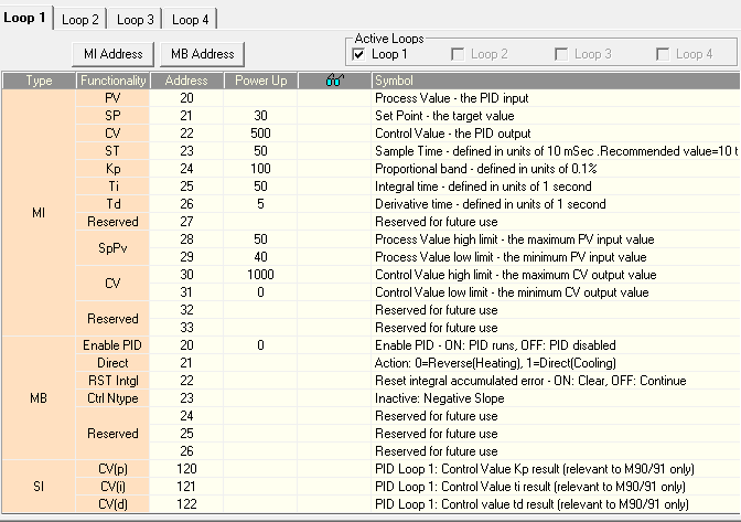
0808THS PWM Output
in UniLogic Software
Posted
Halving the frequency for the second block solves the issue