

sanyc
-
Posts
37 -
Joined
-
Last visited
Content Type
Profiles
Forums
Gallery
Events
Blogs
Downloads
Articles
Media Demo
Everything posted by sanyc
-
Thanks everyone, problem solved and I am now reading very good values. The problem turned out to be in the linearization, I set my Y limits to Y1 = 0 and Y2 = 18000, because I read in the manual that at 1'' the Flow Meter could read up to 18000 kg/h. Eventually I scrolled the screen inside the Meter and found out that at 20 mA it gives maximum 6000 kg/h. So setting the linearization to Y1 = 1 and Y2 = 6000 solved the problem. Thanks again
-
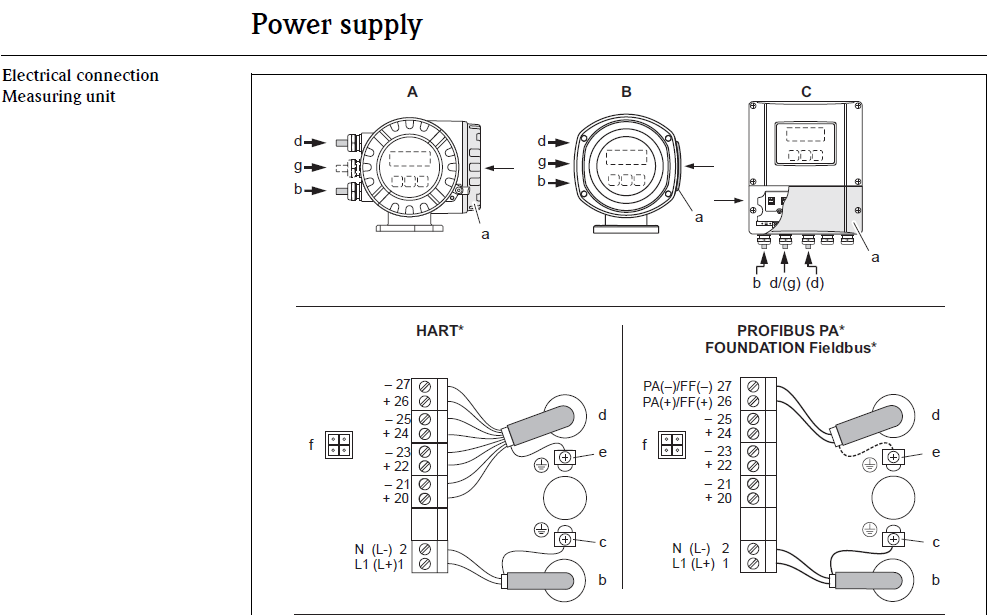
Here are some more shots from the manual: The model I have is designated as: 80***-***********A


-
The transmitter is a Promass F80 Flow Meter. I also have the manual for it. Attached is a picture showing its output signals. My model is the one designated as HART

-
Thanks Denis, Indeed the transmitter has a separate 230V AC power supply. The common on my expansion module is connected to the 0V DC. Then a wire from the (-) of the transmitter goes to the current input on the 0204n card. The positive from the transmitter I 've tried both connected to the (+) and the (-) of the 24V DC supply with no success. Attached is a photo showing what I did

-
I figured the last question; whether its 0-20 mA or 4-20 mA I can measure the current without any flow to determine the value of current so for a 4-20 mA without flow I should get 4 mA.
-
Hi, I am trying to wire a 2 wire 0/4-20 mA analog output Flow Meter to a UIA-0204N I/O module, but It doesn't seem I get the correct reading. The output of the sensor is active. From this I understand that I don't need to supply any DC voltage to the two wires of the sensor, thus one goes to 0V and the other to the input of my card. I also have 0V for the common on my card. Do I also need to include a resistor between the wires of the sensor? Also, being an active output from the sensor the card needs to act like a current sink. How is that achieved? One last thing: how can I easily determine if its 0-20 mA or 4-20 mA if it doesn't clearly specify it on the datasheet of the sensor? Thanks
-
I have problems communicating with the JZ20-JR31. I am using a usb connection (Port COM 10). A serial connection is not an option for me at the moment. So, I manage to establish connection via Controller --> M90 OPLC Settings --> PC Communication Port Settings --> Get Version. Then when I try to download the program it looses connection. 15 minutes ago I was able to download the program but it would still loose connection every 2-3 seconds or so. Now It won't even connect. I tried running U90 as administrator, Nothing. I tried changing USB ports, Nothing. What else should I try? Edit: I am using windows 7.
-
thanks it worked!
-
Hi, Can I use a Numeric Box in Unilogic without its background, i.e: making it transparent? Couldn't find that option.
-
V130 Linearization Issues
sanyc replied to sanyc's topic in Vision & Samba PLC + HMI Controllers & VisiLogic Software
Thank you all for the replies. I had the MI0 link to AN0 in the hardware configuration. The problem turn out to be the pressure sensor I was using. I used another LVDT sensor and it worked great, thanks. -
V130 Linearization Issues
sanyc replied to sanyc's topic in Vision & Samba PLC + HMI Controllers & VisiLogic Software
Forgot to attach the rest:
-
Ok guys, first time attempting ladder programming here using a V130-J-R34. I am using AN0 to get signal from a 3-wire pressure sensor. Brown/Blue goes to +/- 24Vdc and the black wire is my signal. I get a 4-20 mA from the sensor and according to the default jumper settings of the V130 the AN0 is set to accept current as input. I am trying to perform a simple linearization to display how many bars my sensor reads. Since the memory of the analog input is 10-bit this is how I set it up: (see attachment) The logic is that being a 10-bit memory the max 20mA corresponds to DEC 1023 and min 4mA to DEC 204. Then this is converted to 0-10 bars. However it does not work. My MI0 reads always zero and the output MI1 is stuck at -25. Any ideas here about whats wrong? Cheers


