

Juandiaza
-
Posts
41 -
Joined
-
Last visited
-
Days Won
1
Content Type
Profiles
Forums
Gallery
Events
Blogs
Downloads
Articles
Media Demo
Posts posted by Juandiaza
-
-
On 6/22/2022 at 9:04 AM, Flex727 said:
You can always use 8.8.8.8 and/or 8.8.4.4. These are free DNS Servers provided by Google.
Also, that Default Gateway looks a bit suspect. Usually the last number is a 0, 1, or 255.
Hi Flex727, Thanks for your comment. I opened a ticket to Unitronics support because I am still dealing with it and additional of this topic can't connect to the cloud services despite I did all they said in the video section.
Regard of to send emails, I tried all the combinations on DNS section but not success yet. Once I have a solution I will published here to be people inform and get an answer if they deal with something similar.
-
Hi all,
First time I am trying to send an email from my panel, but there is something that probably I am setting right.
Does anybody know what is the DNS that need to setup on Unilogic software? I am using a Yahoo account and What I did from command prompt on my computer. I typed: nslookup Yahoo.com
Addresses: 74.6.143.25; 74.6.143.26; 74.6.231.20; 74.6.231.21; 98.137.11.163; 98.137.98.164. pick up on red color
On DNS Servers Unilogic section: I choose two of the Yahoo servers I found, I guess the problem might be in here. I am not sure if this is setting right. But when I hit a bottom on my HMI to send an email, I am able to see how the status changed to 2 (Function in Progress) and after maybe ten seconds changes to -1 (General COM Error. Please Check the physical connection)
(See pics attached)
.jpg.4ae623e152daa747af69f33bcd44ba12.jpg)
.jpg.11471a1b4a6ccc21cb23ad228a7c171d.jpg)
.jpg.7ebeeab409c5b2d6c5d6b4f6e2ef7766.jpg)
-
18 hours ago, kratmel said:
Hi.
I've reviewed the documentation for your sensor and the Unistream I / O module you have.
I must emphasize that the temperature inputs can be used only in the mV mode in the range of -70mV----+70mV (or use separate passive temperature sensor).
Your sensor has 10mV per 1 degree so you can only see +7 degrees maximum at this input regardless of the settings.
My recommendations - connect the output of the 0-1V temperature sensor to the second analog input in 0-10V mode. It has a 14-bit resolution and you can easily calculate the limits of temperature change with the help of a linearization FB.
Ok,
Thanks kratmel for your response.
Yes, I think it's a good idea. I will keep post the results here and see how it looks like.
-
Hi,
I am trying to set up the temperature over my PLC but I am not really sure How to do that?
So, I am doing this in the same way I set up my 4-20 mA vibrations sensor inputs and this is what I got:
From my Specification sensor:
_302x403.jpeg.e5c38d057e7b7cbaa65e4581ee3f5229.jpeg)
The resolution is 10mV . (Temp from 0-1 Volt will be proportional to 32-212 Fahrenheit)
On the Ladder I have this value from the device:

But When heat sensor up, never changes values.
I wonder, Do I need to linearize my inputs like 4-20 mA?
This is a 4 wires sensor and wire it up this way:

Two of the wire are connected to one module UIS-WCB2 4-20 mA and got the right values. And I decide to connect the Temperature in a UIS-08TC because I am trying to find the ease way to read my temperature on sensors because of the UIS-WCB2 I read this and when I connect them there gave me a weird reading. see what copy from the manual said below:
On UIS-WCB2 Manual said: About thermocouple isolation Although the temperature inputs are isolated from the bus and the module's power-supply port, they are neither isolated from each other nor from the analog inputs. Therefore, temperature inputs isolation may be bypassed when using an exposed-junction (nonisolated) thermocouple in conjunction with analog inputs or another exposed-junction thermocouple, which can lead to flow of unwanted currents through the thermocouple wires that might interfere with thermocouple voltage reading. In order to maintain temperature inputs isolation when using one or more of the analog inputs or when using more than one thermocouple, either: Use isolated-junction thermocouples, or, if you are not using the analog inputs, you may use up to one exposed-junction thermocouple per UIS-WCB2 module; Electrically isolate exposed-junction thermocouples from other electrically-conductive parts of the system.
Does anybody know how to hook up right my wires???
Thanks
Juan
-
On 4/21/2022 at 11:02 AM, kratmel said:
Thank you for posting a solution. If possible, say whether the panel was new (you started with open box) or used (with other project present on it).
It was a used panel.
Juan
-
 1
1
-
-
15 hours ago, kratmel said:
Question: Is the Unistream panel new out of the box?
I encountered a problem when using a not new old version of the panel with a new CPU. The problem was a little different - but I could not overcome this problem. I replaced the panel with a new one from the box and everything started to work.
I just post the solution next time try do it this way.
Thanks
-
15 hours ago, Ausman said:
Is everything wired correctly? Mounted completely and correctly? Double check everything.
Yes I just post the solution thanks
-
Thanks everyone for the comments. Really appreciate your help guys.
I hope that help to someone who deal with this kind of issues that is not in manuals, books, library or so on. In my opinion Unitronics should publish in some where how to do it and people save lots of time.
Just for people to deal with kind of issues I will post what I did with support help from unitronics and it was pretty much what NoamM told me in the previous comment. We open a new blank project with the configuration I/O's right I am describing here:
We installed two Config for the I/O's on Properties Window section (see the picture) in a different Config numbers. I used Config 1 and Config 3 you can choose this randomly (see the other picture). But in one of the Config you will assign the physically I/O you have and then download the project in your controller. Even when physically I have only one I/O module. After that download the project the unilogic software saved on the controller something called "IO DriveConfigVMs's " and then you go to Uniapps and choose over the screen the correct ones that match with your physical I/O and donwload the project that you been working and it Should ready to go.


-
1
-
-
15 hours ago, Joe Tauser said:
Have you tried taking the I/O module off and downloading a blank program?
Joe T.
I did it but the same error.
Thanks for your comment and help
-
14 hours ago, Joe Tauser said:
UniApps is not the iPhone app. (We use that "app" word WAY too much these days. What is the difference between an App and a Program? 😵)
Anyway, if you don't know already you call UniApps by touching the upper right corner of the screen for a few seconds. It's how you check things on a UniStream.
Joe T.
Hi Joe thanks for the info. Yes sorry maybe I didn't explain well. I had used UniApps trying to figured it out what is going on with the I/O and what is happening? I am still learning many things there.
The App what I am talking about in the previous comment it is the one of the three methods that Unitronics recommend to use it to activate a new hardware
First method: Download an application from Unilogic, where the Uni-I/O modules in the application match the Unit-I/O modules physically connected to the controller. (I did it but I have the same error)
Second Method: If this controller is connected to the Internet, go to the Activation Screen and tap on Activate. I haven't done this because I need my controller being connected in Internet and I don't know how to do that?????? I am still learning the way how to connect it but didn't find many information or video to do that. If you know that would help me a lot because I can use these method.
And the third Method will be the one that I am trying to do is: Activate via mobile app. then use this app to scan QR codes displayed on the HMI screen (I don't know where it is locate it ) and the app will issue an Activation Code which you enter into the HMI Screen.
More details about the app they called "Unitronics Mobile Activation App" if you want to Activate a new hardware on the TAB HW Activation in my case I would like to activate my I/O through this app but reading the procedure it says that I need to read a QR code trough the App and follow activation wizard in three steps. My question will be where Can I get this QR code that I need to read from the controller???? you can see more details here below what I said.
https://www.unitronicsplc.com/Activation-FAQ/
In my previous comment I said that only found this App in Apple store for my Iphone but couldnt find it on Play Store for my Android phone which I feel more confident work with.
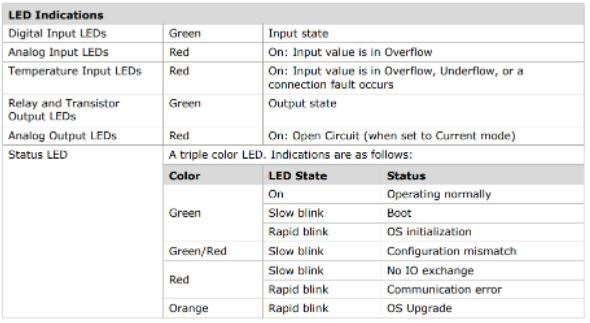
Right now I am stuck in this situation and someone sent me this table to see status if you see this table down here my I/O is blinking fast which means that for some unknowing reason my I/O is not initializing properly.
I upgraded PLC, and did lot of thigs but I am still in the same spot from the beginning.
Thanks for your help and comments Joe.
Juan
-
9 hours ago, NoamM said:
Dear Juandiaza,
Please follow the advice on the popup. Set a new I/O configuration via UniApps, if you do not have any just download an app with two configurations and toggle between then. It should resolve your problem.Hi NoamM,
Thanks for the info. Trying to set a new I/O configuration via UniApps. I downloaded the App for an iPhone which I barely use it. I couldn't find the App on play store for Android's.
Anyways, I downloaded and opened it but my next question will be
Where Can I find the HMI QR code to scan with my camera's phone????? because I need it in order to move on to next steps.
Thanks again
-
On 4/18/2022 at 2:10 PM, Dave said:
try assigning an IP address (from the PLC physical communications tab, such as 10.0.0.61) to your CPU and see what that does for you.
Dave Thanks for the info. I tried but it doesn't work.
-
Hi Joe,
Thanks for your help. But I had tried lot of things but not success yet.
here the program, it keep saying the same error. I updated I/O and PLC. and I tried a new CPU that I received yesterday and the same.
I hope you can help me, I really appreciate it.
Juan
-
Hi,
I am newbie in Unistream world. I used to work in Visiologic environment. I bought a panel 7", CPU and I/O and got this?
Does anybody have an idea what would be the problem? (See snapshot below)
I did the Remote Firmware Update using a USB stick on my Unistream and still with this issue.
It says: CPU configuration file is missing [code 1]
Thanks in advance.
Juan


-
Hi there,
I am trying to stablish communication between the UCR Router and Unicloud. I went to the WEB UI and in Unicloud Tab and using credentials is not stablish communication and I don't understand Why?

Even when you see in the main Overview screen that we have Internet connection

What would be the problem?
Any idea?
Thanks, in advanced
Juan
-
Hi kratmel,
I ran as administrator and doesn't work?
I unistalled Unilogic and Install back again as administrator. (Doesn't work either)
I changed USP setting network and not success. Even when I was able to ping the IP 172.20.10.104 through USP and command prompt.
I was not able to connect through USB port. I am stuck in this issue and thank you for helping me. What else in your opinion should I do at this time?
-
Hi all,
I am newbie using Unilogic and Unistream hardware. I used to get a Samaba and worked with visiologic. So, the first question will be how Can I stablish communication via USB programming cable for the first time. Because when I put communication cable my laptop beeps, like when recognize a new device but never appears when try to download a program. This is the first time to connect my device with my computer. Despite I check usb drives and updated still not success. So, I will appreciate your help with this.
Thanks, in advanced
-
-
Hi everyone,
I am working in a project to send sms with an UCR Unitronic router. Does anyone has made a project using a Ethernet base router. Which SB's operands to use in order to send sms?
Thanks
-
Hi, my name is Juan and I got a UCR router but I want if some of you had tried to use AT commands with it through an emulator If So I'd like to know what did you change in router configuration.
Thanks in advance
-
I would like to work in a project where I can use my samba and get connection using a modem.?
Nowadays is hard to find carriers that provide services in 2G, 3G in the US for the Gemalto EHS6T that Unitronics offer to use with devices. I had tried to get connected in project like send SMS, GPRS but not success. So main carriers like Verizon, AT&T or Tmobile said that those modules are not compatible with their networks.
Some of you Can recommend me a modem that I can use to my project that It had been used recently in the US??????
Thanks in advanced.
-
In my understanding, before to Prepare PLC side modem, I should Initialize PC side Modem first??????? is that correct??????
if YES, when I try to do it with this AT commands below for Defaults: (CINTERION EHS6T modem)
+++
ATH
|||AT+CFUN=0,1 (ERROR)
WAIT 9
AT
<PIN CODE>
WAIT 3
ATI
AT&D1&C1
AT+CLIP=1
AT^SCFG="GPRS/ATS0/withAttach","off" (ERROR)
ATS0=1
AT+CSNS=4
AT^SCFG="Tcp/WithURCs","off"
WAIT 3
AT^SGCONF=540,8 (ERROR)
AT^SCFG="Radio/Band/HandOver",1 (ERROR)I got the last Visiologic Version 9.8.65 recommended by Unitronics Support
The SMS module works good but I need to initialize in order to connect to the PLC via modem and need to turn ON some Memory Bit and create the logic ladder.
I got ERROR in all those AT command (Please see ERRORs in AT command)
I already tested the SMS Module and It works good, and I run some of the AT command like
1) ATI1
Cinterion
EHS6
REVISION 03.001
A-REVISION 00.000.42
2)AT+CPIN?
+CPIN: READY
OK
3)AT+CREG?
+CREG: 0,1
and others AT command, everything looks good but when start to run the AT commands from VISIOLOGIC the errors won't let finish the initialization in order to activate the SB and MB necessary to beging the program.
Any suggestions are welcome
Thanks a lot
-
I will send an email with the ERRORS generated by VISIOLOGIC when I try to initialize this modem.
Thanks Joe for your help.
I appreciate it
-
Because What happens is when trying to run in Visiologic modem services for my modem in this case CINTERION EHS6T and put the correct com port in my case COM1 and so on.
It says The EHST6 modem firmware MUST be version 03.001. For more information click help. But it let me keep moving to next step and when finally hit Initialize PC side Modem
It says:
1- Open port 1 9600,N,8,1 27.- Modem Output AT&D1&C1
2- Modem Output AT (Baud Rate:9600) 28.- Modem Input OK
3.- Modem Output AT +IPR = 9600 29.- Modem Output AT + CLIP=1
4.- Modem Input OK 30.- Modem Input OK
5.- Close port 31.- Modem Output AT SCFG="GPRS/ATS0/WithAttach","off"
6.- Open port 1,9600,N,8,1 32.- Modem Input ERROR
7.- Modem output AT 33.- Modem Output ATSO=1
8.- Modem Input OK 34.- Modem Input OK
9.- Modem Output +++ 35.- Modem Output AT + CSNS = 4
10.- Modem Output ATH 36.- Modem Input OK
11.- Modem Input OK 37.- Modem Output AT*SCFG="Tcp/WithURCs","off"
12.- Modem Output AT + CFUN = 0,1 38.- Modem Input *SCFG:"Tcp/With URCs", "off" OK
13. Modem Input ERROR 39.- Modem Output AT*SGCONF = 540,8
14.- Modem Output AT 40.- Modem Input ERROR
15.- Modem Input OK 41.- Modem Output AT*SCFG="Radio/Band/Handover",1
16.- Modem Output +++ 42.- Modem Input ERROR
17.- Modem Output ATH 43.- Close port
18.- Modem Input OK 44.- Close port
19.- Modem Output AT + CFUN = 0,1
20.- Modem Input ERROR
21.- Modem Output AT
22.- Moden Input OK
23.- Modem Output <PIN CODE>
24.- Modem Input
25.- Modem Output ATI
26.- Modem Input CINTERION EHS6 Revision 03.001 OK
NOTE: pops up and says Modem Operation failed - Modem not Initialized
What Do you think is going on? any suggestion or recommendation?
thanks a lot
.jpg.4ae623e152daa747af69f33bcd44ba12.jpg)
.jpg.11471a1b4a6ccc21cb23ad228a7c171d.jpg)
.jpg.7ebeeab409c5b2d6c5d6b4f6e2ef7766.jpg)
_302x403.jpeg.e5c38d057e7b7cbaa65e4581ee3f5229.jpeg)


I can't send a simple email through my panel
in UniLogic Software
Posted
Thanks for this comment Gabriel.