

Nancygogogo
-
Posts
13 -
Joined
-
Last visited
Content Type
Profiles
Forums
Gallery
Events
Blogs
Downloads
Articles
Media Demo
Everything posted by Nancygogogo
-
Hi everyone, I have a question about the 2.5ms interrupt subroutine, the PLC I have right now is SM35-J-T20 which only has 10ms as the minimum resolution. However, I want to reach the 1ms, so I found a 2.5ms interrupt subroutine to control the output which can control the output with the immediate elements, But I cannot find the example, or how to combine the 2.5ms interrupt subroutine with the main routine. Can anyone give some advice? Thanks.
-
Logic Problem
Nancygogogo replied to Nancygogogo's topic in Vision & Samba PLC + HMI Controllers & VisiLogic Software
I understood most of the time what I need in my program for the valves should be operated by the RESET/ SET coil right now, since what I need is similar to the light switch, not a car horn. As you said for this one, never use the same address twice for a normal coil. Does this mean that I cannot set two same address direct coils in a program, such, if there are two or three different ways or buttons to trigger the coil, is that the right way to put the contacts in OR logic (as Flex said before) and link with same output? Also, is this same for the RESET/SET coil or doesn't matter? Thank you so much. -
Logic Problem
Nancygogogo replied to Nancygogogo's topic in Vision & Samba PLC + HMI Controllers & VisiLogic Software
I am sorry, I am a little bit lost. I got the point what Flex said that for the SET coil, the coil will turn on when the condition is satisfied and will stay on even if the contact opens until the RESET coil is energized. And also for the direct coil, a coil turns ON when the contact is energized, allowing power flow to reach the coil from the net. So in this case, as I said before when the timer is counting, O1, O2, and O3 are opened as well. After the timer is done, all of three output will be turned off until next contact triggers the Output on. Is that correct if I set a SET coil for O0 and O2 in rung 7&8, then place the RESET coil in rung 10 for O0 and O2 (I know that I need to break it into 2 or 3 lines)? Thank you. If I just use the direct coil in rung 7&8 for O0 and O2, what should I do if I want to close the valve by not using the inverted coil, is this possible or it completely wrong? One more question is about check the status of the Output, the logic I want to set up is: for example, check the status of O0, if the Valve is on, then turn off it, if not, then do the next step. I think it probably is unnecessary in the ladder logic right now since if there is no to contact with energized, the output won't be on anyway. Am I correct? Or I am wrong again... Thanks everyone.
-
Logic Problem
Nancygogogo replied to Nancygogogo's topic in Vision & Samba PLC + HMI Controllers & VisiLogic Software
Thank you for all your advice. For this one, the outputs are valves, so the conditions will switch back and forth between ON and OFF either control by user or timer. I am looking at the RESET and SET coil, it seems like I can use RESET coil to turns a coil OFF (unlatch) instead of using the inverted coil. Under both of the SET and RESET Coil, it said do not use a set coil without a reset coil in a program. But can I use a reset coil without the set coil? Cause I might just want to turn off the Valve. Thank you very much. -
Logic Problem
Nancygogogo replied to Nancygogogo's topic in Vision & Samba PLC + HMI Controllers & VisiLogic Software
For this And logic, it's only for the Integer and Long. I thought I can use this structure before. Thank you. Also, For this Coil, when the Timer is done, turn off O1, O2, and O0 at the same time. Is this right? Can I put three coils in series on the same line, or I need to split into three lines? Or I should set them in parallel? I am a little bit confuse on this right now. Thank you.

-
Hi everyone, For the images attached, I would like to achieve that when O0 is on and O2 is off, then will do the comparing step. Basically similar to the AND logic, but for the AND logic, I cannot choose the MB or O. Is this the right way to express in ladder logic? Please advice, thank you.

-
Thank you so much for your help, finally figure out which cable I can use for my PLC.
-
Got it, thank you for your advice. I am new to PLC, so I probably said some words which are not professional, sorry about that... Here's the website where I found the CS25 cable: https://www.colterlec.com.au/product/unitronics-rs232-programming-cable-rs232cb1/
-
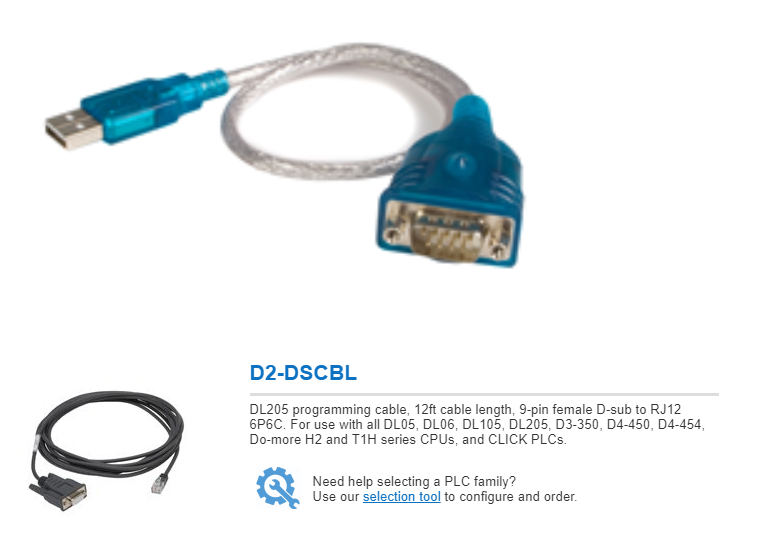
Hi, thank you for your reply. There is a serial port on the samba plc, the cables list before are all the stuff I have right now. So I do need another programming cable (RJ 12- RS232 female). I search online, please see the photo attached, is this what I need for the Unitronics Samba version? And also for the male RS232 to the usb cable, this one shoule be fine right? Please advice.Thank you.

-
Yep, you are right, it said Automation Direct on the cable, so the connection order for 6pins is different from the PLC? I did not receive one from the distributor, see if can fix this problem, thank you very much.
-
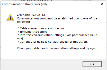
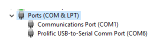
Hi, thank you for your prompt reply. I am using the same setting as yours. And I am using the COM6. Here's the error I got. For the cable I use, please see the photo (last one), thank you very much.

-
Hi everyone, This is the first time I upload the program to the PLC. As the title, I want to upload the visilogic program from PC to the Samba SM35-J-R20 by using RS232 cable, but it shows some errors. I am not sure what setting should I put in Communication&OS setting, and do I need to set the Modem Service as well? Can anyone help on this? Please advice, thank you very much,
-
Hi everyone, I am new to Unitronic PLC, I want to scale an analog input from 0 - 1023 to 0-100. But I don't which logic I can use. Also, do I need contact or coil before the scale? Please advice. Thank you.


