Rick_PN
-
Posts
14 -
Joined
-
Last visited
Rick_PN's Achievements
Member (2/4)
0
Reputation
-
I think so, valves have connectors, supplied by manufacturer with inbuilt shunt diodes. There are some news: today I turned on the RC1 unit (by supplying 24 VDC). It was the same situation - PWR led on, no communication possible. Then I left the unit for 10 minutes and when I came back PWR led was on and I/O COMM. led was blinking. Connection was working too. So I ran Get OPLC Information, response: "EX RC1 A 5.04 (14)". After that I run PLC Status GET and it was in Stop mode. Then I executed Run command and the I/O COMM led turned off, but the Bus COMM. led started blinking. Unit reported that it's in Run mode: What's best to do now to diagnose the problem or somehow to reset it to factory default?

-
No nothing special around it. Just a 10A 24VDC PSU 20cm bellow, two 8 DI and 8 DO units and a hydraulic electric valves, about 70cm away. Canbus cable is in its own PVC 30m long tube, there is about 10cm spacing from the other, power line PVC tube which caries 3phase 20A. Temperature of the installation never goes bellow 10°C. There are no noticeable vibrations.
-
I did check - canbus, serial, supply voltage. I turned it on and off. Then I disconnected it from canbus and try to connect only with serial - no luck (only PWR led was lit). After that I had no better ideas. In the lab I moved all dip switches to ON and I was able to connect via serial (it displays EX-RC1-BOOT). I did try all of those commands Run/Reset/Stop/Initialize&Reset and there is no difference. I downloaded the OS and it seems like this procedure completes with no interruptions (mind that at this point RC1 is still in BOOT). Then I power it off-on or send "Reset" command and after that I still can't connect via serial (PWR led is on others are off). Seems like RC1 can't load OS and go to Run mode.
-
Hi, me again, having problems with Unitronics hardware. This time with module EX-RC1. After 3 months of operation the EX-RC1 module stopped working. CANbus network ceased to work so I had a look at RC1. Only the power LED was lit but I couldn't connect to the module via serial (I tried all bound rates) or canbus. I decided to unplug the module and test it in the "lab". So I connected it to 24 VDC and to serial connection via provided RS232 adapter. Only the power LED is lit and the module is not responding to any "request" via "Communication - PC setting" window in VisiLogic (latest stable version). Then I decided to move all dip-switches (unit ID) to OFF. It made no difference. Then I moved all dip switches to ON -> LEDs for I/O COMM. and Bus COMM started to blink (PWR LED was ON too). After that I was able to establish connection with RC1. I ran "Get OPLC Information " and response is: EX-RC1-BOOT A 2.00 (20). So I suppose this is not "regular" mode? Then I ran PLC Status Get command, response was "Stop, Idle, Idle, Ready, No Error" (unit is in stop mode, flash and memory are idle). I tried to Install operating system (OS V5.04) and all looks like it did the job - status bar for installation was progressing and no error was thrown. But it seems I cannot instruct the module to switch to OS (Run mode), all buttons are grayed out - pic bellow: If I turn module off and on again - there is only PWR LED on and no response from the module (we are back at the start). Its like it can't go to RUN mode. It seems I can't download any program in this "BOOT" mode or factory reset the unit? If I try to download the program I am getting error "Retry binary transmit 1-3 (error0)". How to solve this issue?

-
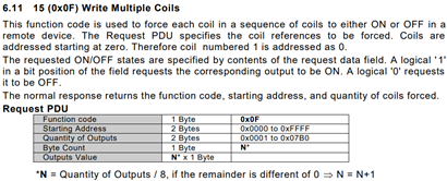
Thanks for your insights. So, if I understand correctly, I was referring to more recent documents of Modbus implementation? http://www.modbus.org/docs/Modbus_Messaging_Implementation_Guide_V1_0a.pdf is from 2004, describing Modbus Request ADU (MBAP Header + Modbus Request) http://www.modbus.org/docs/Modbus_Application_Protocol_V1_1b3.pdf is from 2012, describing function codes and associated functions for Modbus application protocol V1.1b3. Does the V130 supports only older Modbus implementation? Described in the document you posted, which is from 1996 http://modbus.org/docs/PI_MBUS_300.pdf . If we compare “Write Multiple Coils (code 15)” function Request from 2012 and 1996 side by side: Both define Byte Count field – I completely missed that. It appears the folly is with the protocol implementation and NOT V130 Modbus (what was I thinking ofc…). There is one more field defined by 1996 implementation: Error Check (LRC or CRC), is that field still required? “Write Multiple Registers (code 16)” works well and it appears that is because it contains Byte Count field (but no Error Check), which Write Multiple Coils does not. It still begs me why the value in that field has no impact on function execution, if I define Byte Count as 0 or 255, the function executes correctly regardless. Maybe V130 references Length value from MBAP Header and trims command to specified length or sth. Best Regards!

-
Hi! So, I am writing ASP Core 2 project and one of the components is communicating with Unitronics V130 unit (as a Modbus Slave). Since provided .NET Driver library is not portable to ASP Core I need to implement this communication with Modbus. I have limited experience with Modbus protocols but I have used some basic functions in the past – mostly reading Registers and Coils. Just to sample some data. I used python library modbus_tk for this purpose. Using Modbus gives me options for adding more optional hardware down the line. After reviewing some libraries supporting Core I selected library Modbus https://github.com/AndreasAmMueller/Modbus made by AndreasAmMueller, written in C# as Net Standard 2.0 library. I started testing this library by communicating over Modbus TCP/IP with V130 PLC. I got mixed results. - namely "Write Multiple Coils " or "Force Coils " (Function code 15) does not work correctly. So. Modbus read functions all work great, these are: Read Coils (Function code 01) Read Holding Registers (Function code 03) Out of write functions these work great too: Write Multiple Registers (Function code 16) – named “#16 Preset Holding Registers” in VisiLogic help files Write Single Coil (Function code 05) – not referenced in Unitronics (VisiLogic) help files under “Slave Addressing” Write Single Register (Function code 06) - not referenced in Unitronics (VisiLogic) help files under “Slave Addressing” These functions are documented in help files of VisiLogic at “Slave Addressing” topic (where address offsets are defined). Now, function that does not work (at least with V130) is: Write Multiple Coils (Function code 15) – named “#15 Force Coils” in VisiLogic help files This function takes in “n” sequential bit values (“coils”) and a “starting address”. Then it writes these values in slave (in my case V130 device), starting at “start address” and for “n” values. It never sets coils to provided values. But it does set provided coils (addresses) just not to provided values. Meaning, if I want to set 16 coils (lets say some Memory Bits – MB) to 1, only some 8 coils would be set to 1, other 8 coils would be set to 0. It appears that only some byte is set to provided values (but that varies with number of provided addresses/values). Let me repeat again – all provided addresses are written to, just not the values that are provided. Interesting thing is that even if I provide only “true” (1) values, somehow “false” (0) is written to address. AFAIK if I provide only “false” values, no “true” value is written to address. Let’s see what is sent to PLC in next section Modbus implementation on PLC? I suppose Unitronics PLC Modbus implementation is compliant to Modbus specifications and implementation guides, defined by http://www.modbus.org/specs.php (I don’t know, but I would hope). As such Modbus TCP/IP ADU (Application Data Unit) should be implemented as defined in http://www.modbus.org/docs/Modbus_Messaging_Implementation_Guide_V1_0a.pdf and Modbus PDU (Protocol Data Unit) as defined in http://www.modbus.org/docs/Modbus_Application_Protocol_V1_1b3.pdf. This is nicely presented in image bellow – Modbus ADU (MBAP Header + MODBUS request). Here request is made for reading register #5 in remote server (page 22/46 from Application Protocol document): There are 6 bytes of MBAP Header, followed by “length – 1” bytes of MODBUS request (we must subtract 1 byte for Unit identifier, which is included in “length”). In example above there are 5 bytes of Modbus request that makes “length” equal 6. Function “Write Multiple Coils (code 15)” Modbus request is defined in Messaging Implementation Guide at page 29/50: This block is inserted at MOBUS request field in Modbus ADU, presented above. It takes 1 byte to describe the function code, 2 bytes for starting address, 2 bytes for quantities of values (number of “coils” we want to write), 1 byte for number of bytes and finally N Bytes for associated values. Simple test For simple test I am going to use function “Write Multiple Coils (code 15)”, writing 16 (2 bytes in length) “true” (1) values, starting at address 1200, which means Memory Bit (MB) #1200. Device ID is 1. This is Modbus request ADU, which is sent to PLC: It appears that the implementation of Modbus in NET Standard 2.0 library is compliant to Modbus specifications and implementation guides, defined by modbus.org. There is correct MBAP Header and MODBUS request. It provides correct address (1200), number of coils (16) and correct values of coils, which is “true” 1 for all, thus 2 bytes with value of 255. But the result of this operation yields, starting at correct address of 1200: 1, 1, 1, 1, 1, 1, 1, 1, 0, 0, 0, 0, 0, 0, 0, 0. We were hoping for all 1. I doubt its wrong implementation in the library, I have checked many requests against specifications from modbus.org and all seem to comply. Ofc the working functions (Read Coils) etc. all comply to modbus.org specifications and yield correct results. Only “Write Multiple Coils (code 15)” function yields wrong results and is there any chance that its not implemented according to modbus.org? Solution/hack that seems to work I found one hack that seems to work (at least with V130 PLC). But I wouldn’t recommend to use it until there is conformation that this hack does not cause some unwanted consequences. Here goes, it appears that appending one (dummy) byte (of arbitrary value) before bytes that represents values (in the above case [12] and [13] bytes) somehow causes the function to work and we can update Length byte [5]. But it seems that updating Length does not have any effect, it works regardless (need to test that more rigorously). New (working) request would look like this, with added dummy byte: As you can see there is added dummy byte at [12] and length updated to 9. Result of this operation yields correct state - all 16 coils MBs are set correctly. This seems to works with any combination of values and number of coils. But this hack is untested, I don’t know if this command is really contained to just defined addresses or does it write all over the memory. I tested this only for some addresses beyond defined range by manually setting values via VisiLogic “online mode". More importantly, why does this hack work? Or even more, why “normal” Write Multiple Coils (code 15) does not work? Is this V130 specific? Any help appreciated! Best Regards! PS: To add, I did change "MODBUS: SCAN_EX" block to SCAN and SCAN_32 - nothing worked. Now I left it with "MODBUS: SCAN" block to support "older working applications" as stated in help files of VisiLogic.


-
V130 problem with Ethernet
Rick_PN replied to Rick_PN's topic in Vision & Samba PLC + HMI Controllers & VisiLogic Software
I agree. That is why I posted new post with very short summary. But for future readers I think its more convenient to have the solution included in original (first) post. If they want they can scroll down to read other responses and discussion. The forum its less readable if the solution is buried between posts somewhere. -
V130 problem with Ethernet
Rick_PN replied to Rick_PN's topic in Vision & Samba PLC + HMI Controllers & VisiLogic Software
Turns out V130 does not like some routers and I was unfortunate to have 3 of them. I edited the first post for more detail. I would like to say thanks to all who spared their time on my issue. -
V130 problem with Ethernet
Rick_PN replied to Rick_PN's topic in Vision & Samba PLC + HMI Controllers & VisiLogic Software
Good points. But as mentioned I already switched cables and networks and the same thing happened. But worth a try. It could be damaged, but nothing specific ever happened (like lightning strike or other power network related faults). I will check connections of the ETH module again. Weird thing is that It can work 1h, 1 day, non-stop, but then I download new project (via Ethernet) -> after downloading PLC RUN command is send -> sometimes Ethernet works (green LED is lit and orange LED is blinking). But other times (~20% chance) Ethernet does not begin to work (green and orange LEDs are lit - no blinking), even if it worked while downloading the project, just a few sec before. Ethernet never breaks while it is downloading the project or while I am connected with "Online Test" in VisiLogic. -
V130 problem with Ethernet
Rick_PN replied to Rick_PN's topic in Vision & Samba PLC + HMI Controllers & VisiLogic Software
I think datasheet https://unitronicsplc.com/wp-content/uploads/2015/12/V100-17-ET2_S_TECH-SPEC_10-13.pdf states that for PLC-PLC one needs crossover, but shouldn't that apply for PLC-PC too? Will try to clean the code and run just this segment and then add complexity. Subnet is OK. Is there anyone on this forum with more insight into hardware of ethernet module? -
V130 problem with Ethernet
Rick_PN replied to Rick_PN's topic in Vision & Samba PLC + HMI Controllers & VisiLogic Software
That really is unfortunate. Will do. I had many combinations of connections before and it was getting the same behavior. But true, wasn't my priority to solve the issue back then. I don't have another PLC or Ethernet card. It would be nice to get some information from hardware support if this is known issue and if some DIY fix exists (capacitor, resistor, diode or sth). After all it's a 70€ module (V100-17-ET2). From the look of PCB it shouldn't be complex ofc if only there is no defect in chips/ICs. -
V130 problem with Ethernet
Rick_PN replied to Rick_PN's topic in Vision & Samba PLC + HMI Controllers & VisiLogic Software
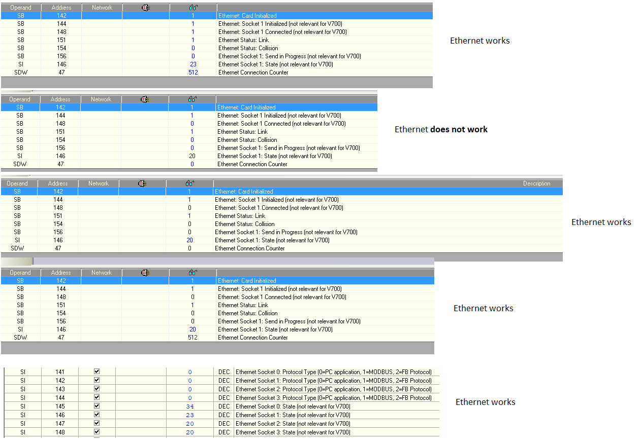
I edited the first post with additional information. My posts need to be approved by a moderator and that takes time (8 hours+). @Joe Tauser I am aware of SB168 and SI104, both would not be there if the Ethernet would work. Same goes for Socket 1. Yes it is. It is the same router - PLC on LAN cable, PC-LAPTOP on WLAN. - this is "setup1". I do use other "setup2" which is - PLC on LAN, PC-Desktop on LAN (switch 10m away). Switch and router are connected via cable. And this connection experiences the same problems. You mean like a crossover cable, direct connection PC-PLC? Thanks for the initialize tip with MB0. But the strange thing is that it appears initializing is not the problem as this is successfully done. Why would it start working only by re-pluging the cable? What happens when the cable is re-plugged? I attached some screenshots of parameter watches (via Serial connection) when Ethernet works or does not.
-
V130 problem with Ethernet
Rick_PN replied to Rick_PN's topic in Vision & Samba PLC + HMI Controllers & VisiLogic Software
Thank you for your answer. I added startup block parameters in the main post and added PLC OS version - 4.4 (31). I am aware of all your points. I am using this blocks to test some performance (SI104) so they are there for this "debuging". When you get this random incoherent disconnects anything is a suspect. In some "official" example files SB168 is set like this (in some isn't) and clearly it does not solve my issue. Thanks for the tips anyway! Best Regards! -
Hi, (Edit: For convenience, the final solution of this issue is at the end of this first post) I am having problems with ethernet connection on V130 (33-R34) OS 4.4 (31) with V100-17-ET2 ethernet module. Problem is that sometimes (mostly random) connection somehow breaks and I am no longer able to communicate with V130 (using Visilogic) via Ethernet. To be more precise: Ethernet connection sometimes breaks after downloading the project (after RUN command is send). I don't have the data on how the Ethernet behaves when PLC is running for a long time - this project is new and I have been able to test it only for some days. But as for now I have never get disconnection while running "Online Test" mode or while downloading the project (just right after downloading). But while programing V130 and testing the project/program (for the past week or so) I noticed that after downloading the project sometimes Ethernet would work right away but other times wont. This even happens if there are no changes to Power-up setup of Ethernet. There is no difference If I Burn the project or just Download it. It happens when the PLC restarts and it’s about let’s say 80% chance that it will work and 20% that it won’t. Which is really frustrating because I cannot rely on this to be able to program or control the PLC remotely. What usually works to reestablish the connection is to power off and back on the PLC (not great) OR to just un-plug the Ethernet cable, wait a few sec and plug it back in. Sometimes I need to wait ~2sec before plugging it back in and sometimes ~5sec for the connection to work again. My initialization process is presented in attached file. I had shuffled the “PLC NAME”, “TCP/IP” etc. blocks in all combinations and nothing works. Maybe it’s a network thing (but if I recall it correctly I had similar problems when I started using V130 and learn how to use it on my home network, but I shrugged it off as “beginner problems. Nonetheless I added PLC IP and MAC on my DHCP list (as static address assignment), but this didn’t resolve the issue. How can I fix this issue? Any help appreciated. EDIT: Parameters of above presented blocks: It's pretty much the "default". Physically the other end of Ethernet connection is a router (build-in switch), right now I am using Visilogic (via wireless) to connect to PLC and sometimes Remote Access. EDIT2 (22.10.2018): I apologize for delayed responses but my replies are moderated and need to be approved by a moderator. Solution EDIT3 (19.11.2018): After hours of testing, downloading, changing cables, making cables I decided to try more routers. As is often the case, the problem was "easy to solve". It appears some routers aren't friendly with PLCs network card. I tested 4 routers: ASUS RT-AC1200G+, Fritz!Box WLAN 7360, Buffalo G54 and LevelOne (only a switch). All of these devices don't cause any problems while only PCs, Printers, TVs are involved. Everything works as it's suppose to. But, three of them: WLAN 7360, Buffalo G54 and LevelOne are not compatible with V130 PLC. If I connect V130 to any of those I get problems that are described here in this topic. LevelOne, Buffalo G54 were my old devices that is why I was having problems with ethernet when I started learning with V130. ASUS is my latest upgrade so I decided to bring all of these 3 devices to the site where V130 is installed and test all of them (WLAN 7360 was already on the site). It is strange that 3 out of 4 devices didn't work. Maybe there is a problem with some old devices or sth. Newer device (ASUS router) worked perfectly, right away with no modifications to the program. Debugging this kind of problem is tedious because one does not simply have 4+ routers to test with on remote sites. I am pretty sure this is a solution because I didn't get any error in one week of testing. Thank you all for your guidelines and solutions.