

Borec
-
Posts
3 -
Joined
-
Last visited
Content Type
Profiles
Forums
Gallery
Events
Blogs
Downloads
Articles
Media Demo
Posts posted by Borec
-
-
Hello,
thank you all for quick responses. After your suggestions and contact with Unitronics support I created a final version of my program.

Unfortunately, there are no received messages. Messages are received only during power-up of the converter (some noise).I checked my cable - there is galvanic connection between pins and endings. I also swapped cables many times.
Here is the oscillogram of the Modbus signal at drive inputs.

And below oscillogram when I connect with my testing software (and it works). I know that probe's polarization is inversed. What concerns me is that the amplitude of peak-peak voltage above is 2.5V when it is 7V below.

Modbus in my drive works properly as I checked it by modbus testing software on my PC (checking means sending and receiving words and operating drive remotely). BTW. Mtester - great and free software. Register which I try to read (2101 in drive, so 2100 in PLC) has value 65 - no matter as there are no received data.

MI 2 status is 4 and 5 alternately.
Termination is done at both ends.
Do you have any other ideas?
Once more - when I want to set PLC Net ID with this block, numbers from 1-63 are CANopen and from 64 RS485? Does it have meaning? In my program, PLC is 1 when drive is 2. I tried also 64 and 65 with no success.

KR, Bartosz

-
Hi all,
it's my first post but I guess not least as I have a project to do using my Unitronics V1210 with CANOpen and 2 ports for Modbus RTU on board.
I want to establish basic communication with my VFD (Vacon 100 / now Danfoss company) by Modbus RTU.
1. I bought RJ11 six pin plug and prepare junction so I have two cables - yellow at PIN1 and red at PIN6.
2. I connected PLC (Port 1) to VFD (A,B inputs)
3. I wrote a basic program to read the register 2101 (which is not 0 for sure) and... nothing happens. No communication.What I have checked:
- Ports termination (set to RS485 with termination)
- Galvanic connection between pins and end of the cable and it is ok
- loopback test FB - no answer
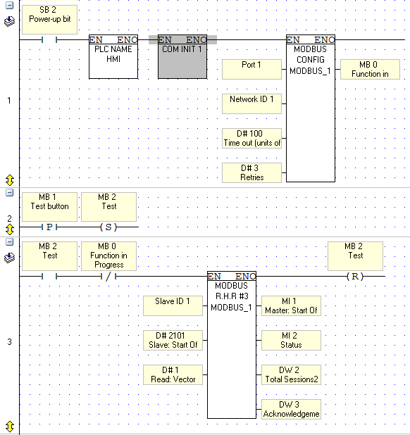
- ID, Baud Rate, Parity, Stop Bits - they are the same in drive and PLCI kindly ask if someone could check my ladder diagram as I have no idea what is wrong.

KR,
Bartosz


Unable to communicate by Modbus RTU
in Vision & Samba PLC + HMI Controllers & VisiLogic Software
Posted
Hello,
thanks for support. I tried everything and finally helped... actualization of the software.
I downloaded the the latest version of Visilogic 9.8.79 and updated the PLC OS, now it works.
KR,
Bartosz