Dancho
-
Posts
16 -
Joined
-
Last visited
Content Type
Profiles
Forums
Gallery
Events
Blogs
Downloads
Articles
Media Demo
Everything posted by Dancho
-
Request for commentary- Calculating volume and 'timestamping'
Dancho replied to Dancho's topic in UniLogic Software
Volume is simple to calculate. I will likely include the flow rate on the HMI some place for the operator, but until I have it worked out just right I don't want to bother. I made an attempt at calculating flow rate and had issues with sizes of tags (also used a different approach previously). The flow rates I'm calculating are between 0 and 4 GPM...Much easier to write some javascript to do some arithmetic in Node-red, then send the data off to a database... -
Good morning all! Happy Thursday! I've got a rung I'm modifying and wanted to pass this by as many eyes as will look. I think it will work, or is very close to working as intended, but I wanted to solicit as much feedback as I could about the approach, any stylistic feedback, etc. [I read a post this morning where Flex727 implored a forum member to put together programs with 1:1 networks to rungs. My program was not done this way, and I realized I may be learning bad habits, which are probably easiest to break at this point in the learning curve. Hence, this post.] Here is the original rung. It closes a valve filling a tank when the percentage is greater than a set point, and opens to refill when the percentage is less than a set point. Here is my modifed rung. It is large, but should be straight forward, I hope. H1_JH_OUT is the measured level of the tank before converting to percent, UINT16. I grab the RTC mins, secs and hours, multiply out, add all to the seconds time, and store that as either the time it topped, or time it bottomed. When it bottoms, I subtract levels and times, with the idea being that I can send those via MQTT to my network and calculate GPM from that. (Tanks are mostly constant cross section). The set and reset is because the tank level being greater than or less than the set points is not momentary and I wanted to make it a one shot timestamping and measuring. Any helpful critiques? Thanks in advance!


-
That is an option as well.....though I did try it. The arm is made of round stock, and the reflection from it was throwing an error in an extremely wide and random range. But always up...which is why I landed on taking the minimum element of an array. Now, if you wanted to share the averaging example I am ALLL eyes and ears.
-
I haven't found anything about integrating an I2c sensor with Unistream. Is this a no-no? Or is the practical way to have an intermediary device communicating via serial or otherwise?
-
Speaking of cycle times...I've wondered if there is a way to measure cycle time of a program? I can do it in Python...😝 Does it particularly matter, or should I assume that I will always get a reasonable cycle time unless I'm doing/something has gone terribly terribly wrong? I assume the watch dog timer on a PLC has to be extremely short as well?
-
Fantastic. That is very helpful. I can appreciate 'almost never'. That being said, my program has evolved over time, 2 different system integrators, and now me. There are real numbers used in several places...generally related to drives and encoder outputs, speed, etc. Is this the 'right' time to use real numbers, or just another way to handle those things? I'm actually just converting from displacement/position to volume. Little bit easier, but I will keep this in the back of my mind.
-
Good morning and happy Friday to all! I am still learning the ropes of PLCs ladder logic, etc and I am hoping to get some suggestions. I am from the world of traditional code-writing and microcontrollers, so the handling of arrays and datatypes within ladder logic has been a bit of a learning curve. Here's my situation: I am using a 4-20ma signal from a laser to measure the level of a material within a tank. The tank has a rotating arm which periodically passes through the laser beam. To filter this out, I am taking a measurement every .1 seconds and writing it to the 0th element of an array (after shuffling the rest of the values). I am taking the minimum element of that array as the true level at that moment (arm in front of the beam will only make the measurement appear higher, never lower). I am taking the 'true level'/minimum measurements and writing them to another 10 element array every 0.1s, same scheme, shuffling, etc. I have a third 10 element array in order to do calculations on the rate of change from the 0th element to the 1st, 2nd, 3rd, 4th, etc. Essentially I am working to get the volumetric flow out of this tank.... The issue I'm having is that I am getting only whole numbers, and non-negative numbers. The order of magnitude and precision should be X.XX. I am only getting the integer portion, unsurprisingly. I used a formula function block and did my calculations in there. Very handy. Avoided me having to add another function block to divide by 0.1, 0.2, 0.3, 0.4 etc. (Also, that was giving me datatype errors using the MULT function block). I realize I've given a lot of details and not asked any questions directly, so here goes: 1. When is the 'right' time to use real numbers? 2. Given I only need 3 significant digits of precision, should I multiply my values by 100 or 1000 and format it on the HMI to show the decimal place? 3. If I want to know both positive and negative values, should I use multiply by 100 or 1000 AND choose 32768/2 as the zero point? As in, shift the values, so that below 16384 represents a negative volumetric flow? 4. Are there better ways to handle arrays than creating multiple arrays just to store 9 elements, then move them back to the original array, or copying a whole array just to run numeric operations? For example, is there a clever/elegant way to calculate the volumetric flow from the 0th element to the 1st, 2nd, 3rd, so on...getting 9 values and averaging, sorting, etc. to get a less noisy signal? Kindest regards!
-
Connecting Unistream to LoPy via Panel USB Port
Dancho replied to ETURSON's topic in UniStream: Hardware
I hate to revive this topic, however, I'm continuing to have issues related to serial TX from the USB host port. ....Frustrating. I took my working project, added two messages to be triggered once by the General.Initial Cycle bit aaaand....ALL the serial TX ceased to work, not just the boot up message. My MCU is set to flash the onboard LED when Serial.available() = true. I'm imagining it is detecting the voltage drop for the first bit. That happens and happened with the previous issues, however If my MCU sends any MQTT messages at all they are almost entirely 0x00 and few 0xff. Message sizes are between 21 and 68 bytes. The flow control scheme was the following, increment a counter every second, loop to 0 when greater than 8. Send a specific message if the counter is 2, 4, 6 or 8. When the initial cycle bit is 1, start counter at -4, send a specific message at -2 and 0. Previous working project had 1 CPU Protocol Message, 4 total messages, no checksum, no STX, ETX: 0x0A. Non working project has 1 CPU Protocol Message, 6 total messages, no checksum, no STX, ETX: 0x0A. In online mode the rungs get powered at the correct counter increments. Am I supposed to see the rungs turn red the whole way to the end?? Other things that were different/ correct actions taken: I added a ladder just for message sending rungs, and added it to the main routine. I made other changes unrelated to Message Composer. When I tested the serial comms and noticed the issue, I removed the initial cycle rung. No change. I removed the additional messages. No change. I removed the additional ladder, and replaced the rungs on the ladder from the working project. No change. -
I am familiar with Moxa. I will take a look into that. The system integrator who built this system years ago put in an unmanaged, wired switch. We had SEW Movitracs which were Ethernet/IP (I believe), and the URB-TCP. His response to an email regarding connecting the PLC to our network was that it would require a managed switch. Maybe something with IP address assignment???
-
The project I've been working with has an unmanaged switch, and thus has not been connected to our network. While searching for a solution to another issue involving the USB Host ports, I believe I read that a typical wifi adapter can be connected to the PLC. Is there specific hardware that is suggested? I'm looking to use it for MQTT pub and sub, mostly, possibly VNC.
-
Connecting Unistream to LoPy via Panel USB Port
Dancho replied to ETURSON's topic in UniStream: Hardware
Solved. Even with an appropriate buffer size, the string length apparently affects the stability of the serial TX from the USB port. Below some threshold (haven't pinpointed the exact size), the serial comms are hit or miss. (String length is roughly related to number of tags within the strong, so that may also be the culprit) Previous buffer size was ~125ish bytes, and full string showed with a USB-RS232 and RS232-USB, but nothing on the Prolific device, etc. Now two strings ~75 bytes reliable communicate with a CP2012, PL2303TA (prolific) no problem. I'm at a loss for why, but that's what I've found... -
Connecting Unistream to LoPy via Panel USB Port
Dancho replied to ETURSON's topic in UniStream: Hardware
I got the EEWriter tool to invert signals if needed. It seems to have an authentic chip. VID and PID seem fine (devicehunt.com confirms). It says EEProm not written yet, though I'm not sure why that would make a difference... I also used the Prolific CheckChipVersion tool, and it doesn't appear to be counterfeit? Beyond that, my next guess is possibly STX and ETX on the string? Though I did not need them previously, as I mentioned, all serial comms were fine.

-
Connecting Unistream to LoPy via Panel USB Port
Dancho replied to ETURSON's topic in UniStream: Hardware
I've tried a faster baud rate and a lower delay. I have not shortened the string length. Buffer size is adequate I believe. No change. I am very hesitant to point towards the PLC as the issue, but I am starting to lean that way. Especially since it worked flawlessly during the first boot up, then never again. Is there a way to rule out driver issues/ Prolific chip authenticity? What about flow control? Is there anything I could be missing? For reference: USB to TTL converter (https://www.amazon.com/gp/product/B07R8BQYW1/ref=ppx_yo_dt_b_asin_title_o00_s00?ie=UTF8&psc=1) -
Connecting Unistream to LoPy via Panel USB Port
Dancho replied to ETURSON's topic in UniStream: Hardware
My TTL 3.3V converter arrived. All worked well for about four hours. During that time, I updated the program on the PLC and combined the output strings from 4 into 1. Since then, my serial broadcasting device can't make out a single character from the PLC USB port. The TTL converter has a PL2303TA, and I think I've ruled out that the signal 'became' inverted, or otherwise. Using a USB-RS232 and an RS233-USB I've confirmed the string is transmitting. My next steps: Change to a faster baud rate (19200 -> 115200) Lower delay time (50 -> 5 mS) .... Shorter string/multiple messages? I've got a terrible oscilloscope, but it's enough to measure voltage levels. Is there anything I can do to suss out what my MCU is seeing? -
Connecting Unistream to LoPy via Panel USB Port
Dancho replied to ETURSON's topic in UniStream: Hardware
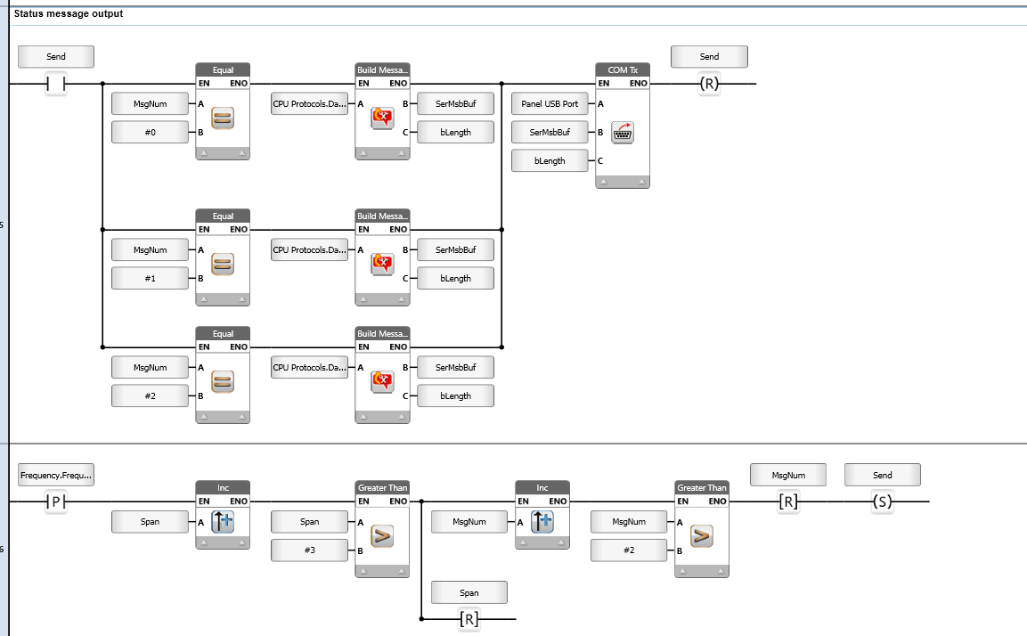
Prolific is what is supported, however I assume it is not unheard of for other hardware to work sporadically? This is what I'm waiting on (https://www.amazon.com/gp/product/B07R8BQYW1/ref=ppx_yo_dt_b_asin_title_o00_s00?ie=UTF8&psc=1). Do you think this is what I need? Here is my ladder for outputting the message(s) and the setting/resetting "send". I think I have an issue with my algorithm for cycling through messages. Shouldn't be a hard fix- it only sends the first message, never cycles through which messages. (I changed the original message to a few smaller messages in case the length was causing problems for my MCU. It was not. May change back). I appreciate the help. Ladder is new for me, but I've got lots of programming and electronics experience otherwise.
-
Connecting Unistream to LoPy via Panel USB Port
Dancho replied to ETURSON's topic in UniStream: Hardware
I really hate for my first forum post to be resurrecting a dead thread, however I'm doing this identical thing and having issues. Eturson, did you get this working? I am using a CP2102 converter chip on an ESP32 dev board (https://docs.zerynth.com/latest/official/board.zerynth.doit_esp32/docs/index.html). Amazon will be delivering a PL2303 USB to TTL adapter this afternoon. I'm hoping this fixes me. I initially had all working well directly from the USB host port to the micro-USB on my dev board. This worked until the next time the system was turned on (???).