Search the Community
Showing results for tags 'TCP'.
Found 20 results
-
 Hello, I've recently acquired the UCR-ST-B8 router from Unitronics. The set-up was easy but it won't communicate with other devices. My goal is that the router is connected to a PLC through a direct ethernet cable and that the PLC can read the status of the router, effectivly making the router a slave of the PLC. I also want to recieve SMS messages on the router and the PLC to read those messages. *Note I did change the IP from 192.168.1.1 to 192.168.0.1 With a cable in LAN 1 of the router and the other end in a laptop we can connect to the webUI. Here (Services-->Modbus) I've configured the router as a modbusTCP slave and did save the settings. After this I close the webUI and connect to the router using QModMaster (https://sourceforge.net/projects/qmodmaster/). With this program I should be able to read the registers of the router. (I know this works as I've used it before) But when I try to read the registers it doesn't get a return signal. After this I've tried it using a PLC. But I am not really familliar with the Unilogic enviroment so I'm having a bit of trouble setting it up. As stated earlyer I want to read the data from the router and recieve SMS messages from the router and read those using the PLC. Would I need to setup the router as a router or as a modem in the Unilogic enviroment? Further if I set it up as a router would I need to take extra steps to read out the UCR-ST-B8 or should I be able to read all the data immediately? So the questions I have are: How do I read out the router? What settings need to be configured. Is it possible to read the data using a PLC? I'm using a USC-B5-T24 and how would I do that. Should I use ModbusTCP or Modbus RTU rs485?


-
 So i am currently looking in to the possibility off sending strings (probably between 20 and 32 characters) to a v560 plc over modbus TCP. The purpose of the string is product name/version that is going to be produced on the machine where the v560 is installed. So the operator can easily sees if the right parameters are loaded. currently we do this with a 7 to 10 digit number but a mistake is easily made. How i am thinking of achieving this is by converting the string to ASCII and writing it to 16 integers. Then in theory i could use ASCII string variable to display the name on the HMI. For the moment i dont see any problems with the setup, but before i start writing the program i thought i might be smart to ask around here for other opinions. maybe there is a smarter way to do this?
 -
I have made a program for a Unitronics PLC to communicate with another PLC (sigmatek) over TCP. Unitronics is the server, the sigmatek PLC is the client. I am sending a big data table over TCP (5120 bytes in total). The way it works is Sigmatek initiates a connection as a client, and unitronics sends the data once a connection is established. I have it working, but I'm not statisfied with the way it is programmed now. Let me try to explain my problem: For some reason I cannot send more then 1024 bytes with one TCP server TX function block, so I have split the data up in 5 seperate buffers, that I send to 5 clients. (I have configured 5 clients in the other PLC), these 5 clients all connect to the same server. This is no problem for me. The problem is, that to send the buffer to the correct client, I need to know the client ID. What I'm doing right now to figure the client ID number out is: In the sigmatek PLC I have made a program that the first client has to connect, and when the first client is connected, connect the second one after a small delay, and so on.. In my Unitronics PLC, if a new Client is connecting, I can check the ID of that client by checking the connection array (it's an array of 16 bits). For example: Sigmatek tries to connect the first client, if the connection is esablished, then bit 4 of my connection array in Unitronics might become high, now I know Client 1 has ID 4, when the second client connects, bit 2 might turn on, so the second client has ID 2, and so on.. and when a connection is lost, I disconnect them all and start the process again This works fine, but is far from elegant... What's the proper way to find out the client ID on the server side of a TCP server / client model?
-
On upgrading my Unilogic program with compiler version 1.29.111, it now reports this error: 'The TCP Remote slave limit of 64 operations has be (sic) reached. (136)' The program previously compiled successfully with compiler version 1.29.26 and .34. I have 11 ModBus Remote Slaves on separate IP addresses, with 10 of which I request a single 64-register transfer, and the eleventh two 32-bit register transfers. If I remove all the Slaves and associated code, then the program compiles. If I then reinstate them it now compiles successfully! I have several versions of my program in development, chasing different operational problems. Do I have to repeat this procedure for each of them in order to use this latest compiler? Regards Robin Proctor
-
Hello, I just have a small problem, and I keep on asking some simple stuff, because I'm new to Unitronics, and programming PLCs. I have a JZ20-J-UA24, and I want to read from it, and write via labview. This requires a modbus configuration. I looked at the sample modbus configuration on that unitronics supplies with U90 ladder, and some modbus forums on unitronics, but didn't clearly understand what to do next. So suppose I want to read on labview the temperature measured via a KTC connected to the PLC's analog input channel 1 displaying its value at the level of MI 19, how can I do that? And can someone explain the configuration of the PLC because I didn't get alot what's going on, or how even to read the IP of the PLC.
-
 Hello, I have JZ20-J-R16, and I want to read values from output 1 on labview, but I just have a problem in trying to do it. My PLC doesnt have an Ethernet port, I can just connect it by means of a USB, or com port to my PC. So if I wanted to read from this PLC on labview by means of RTU communication, can someone please give out an easy code to do that (to configure the PLC, and thus assign the addresses to each port)? And if I bought an external mode that contains an Ethernet port and connected it to my PLC, would I be then able to communicate by means of TCP through labview? I need help on this ASAP pleasee
 -
Hello, I am writing a communication program. I receive a string of data and need to compare it with a couple of parameters. Anyone? example : i receive : /X354,Y653,Z345/ my PLC needs to recognize : /X... , Y..... , Z.... / in the future i also need to parse this and display the values in different text boxes. thx in advance
-
Hello, I am a new programmer in Unilogics. After I got to know Unilogics , I have to set up an TCP/IP connection. The PLC is the server. I already programmed a function for sending information to the Hercules ( on my laptop). Now I need to receive information back from my Hercules. I have tried a lot of options but it will not work. The Rx blocks count the right amount of byte's that is received. The problem lays ( I think) in the fact that OUT E from the Rx box doesn't go to 1. Also I dont get BOX E from de parse message box. If i made a scanned message for receiving it isn't standing there. I find it very strange that i find it so easily to send info but then it wont work to receive info. thank you for the help in advance NOTE: " BUFFER ONTVANGEN MEANS BUFFER RECEIVED" im dutch haha


-
Hello, I am a student , also in PLC programming. After I got used to Unilogics I got a internship order. I need some help with TCP data Rx/Tx, especially with the programming ladder blocks. My program is now so far working that I can see that my PLC and Hercules ( on laptop ) are connected but then i can't get it working. First up i want to try to make a very simple light lit up when i received data. So I had it configured like in the image. The day before I programmed it like that I was able to see the quantity of byte's that was received in box D. But today with de configuring in the image that isn't even working. Questions i especially have : - The block does need to know when (at how much byte's) the box E (remote IP) it must power up, right? - I really want to know what the functions are from the I/O's of the TCP SERVER Rx/Tx data block? Can someone please explain it in more simple language? thanks for help in advance
-
Not so familiar with TCP_Client_Server in Unilogic. Can this be used to send AT commands to a device? I have a Bgan SAT unit with built in gps. I can telnet a AT command from my pc and receive the gps co-ordinates.
-
 At random times sockets 0 and 1, 20255 and 20256, server (slave) on V430 and SM43 are freezing up. Usually not both.... thinking it's more port 20255. I've played with the SI for timeouts. SB168 is set to power up at "1". it will still email, web server (V430) will still work, and usually port 20256 will work to let me connect and remote REBOOT the PLC, then the frozen port comes back to life. Any ideas!? I worked a long time on getting a reliable "EMAIL" logical construct; I believe I got that whipped and have had no issues lately. This STICKY PORT issue has plagued me for sometime. Any suggestions/solutions would be greatly appreciated.
 -
 Hi. I'm an experienced PLC programmer but I'm new to the unitronics universe. I'm wondering if anybody can give me an example on how I can send and receive text strings over TCP client interface? I'll be using a UNIStream PLC to communicate with a robot arm using a TCP connection. I would like to connect to the robot on port 29999 to send different commands. The robot will then come with a reply. For example: Command sent to robot: "load <robotprogram.file>" Return value on success: "Loading program: <robotprogram.file>" Return value on failure: "File not found: <robotprogram.file>" "Error while loading program: <robotprogram.file>" The Ladder functions "TCP Client Tx", "TCP Client Rx" and "TCP Client Connect" is not documented in the help file... What's the correct way to use string data as buffer source or buffer destination? I will appreciate any support!
 -
I'm attempting to communicate with a server (robot) using TCP Client Connect, Tx, and Rx. Upon making ladder logic changes, and re-downloading to the PLC, the TCP Client fails to connect (Socket State = 3, Is Connected = 0). If I change the IP address of the Panel/CPU, it works again. At first I thought this might be an issue with spamming the TCP Client Connect function, so I changed it to only run once upon startup. No luck. I also tried running a TCP Client Disconnect before the Connect with a time delay between the two. No luck. What ever changes I make, if i change the IP addresses, it works again.... Any suggestions are appreciated, thanks! ****UPDATE**** If I download a new program to the PLC before running a TCP Client Disconnect, the next time I try to connect, it doesn't work. If I download a new program to the PLC after a successful connect and disconnect, the next connect works no problem. If I download while connected, the server must be power cycled before the connection can be reestablished. This shouldn't be an issue for the actual application, but it means that during programming and testing, I have to disconnect from the server before I make any changes. Sounds like maybe the sever is holding the socket open while the new program changes are being made to the PLC? Then when the disconnect runs upon wakeup, it can't close the previous socket. Any comments?
-
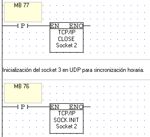
Hi everyone! I´m using the four sockets in a Vision 130, and I need more! So, I tried to redifine a socket in run time according to some conditions, but I find out that once the socket was defined, I can´t redefine it. The socket is first initialized as TCP / Port 502 / Server. A Modbus IP configuration is attached to this socket, and running as Modbus IP Slave. Then, I close the socket... ...and redefine it as UDP The result is that the socket never loose the Modbus definition, and can´t connect via UDP. When the second socket definition is executed, the socket state goes from 20 to 34. If I insert a reset of the PLC before the second definition, all runs correctly. So, I think that the only way to "release" the socket definition is restarting the PLC. Is this right? Or (more likely) I am doing something wrong? Thank you very much!!


-
Hello, I'm having an issue with getting the .NET driver to connect and read values. I am having no problems connecting using Visilogic, but when I take those properties and use them in the .NET driver they don't seem to be working. The interesting this is that I'm not getting an exception, so my application believes the driver is connected, but looking at the properties for the Ethernet object it appears not to be. When I put a break point on the oPLC object, it states that the object could not be evaluated because the previous function had timed out. When run it down to the last line and check the response values it is null. Here's the code: Ethernet ethernet = new Ethernet(_cell1PLC_IP, _cell1PLC_Port, EthProtocol.TCP, 3, 3000); PLC oPLC = PLCFactory.GetPLC(ethernet, 1); oPLC.SetExecuter(OperandsExecuterType.ExecuterPartialBinaryMix); // Create the write request // ReadWriteRequest[] readShifts = new ReadWriteRequest[1]; readShifts[0] = new ReadOperands { NumberOfOperands = 1, OperandType = OperandTypes.MB, StartAddress = 0, }; // Extract the shift times // object[] shiftTimes = ((object[])readShifts[0].ResponseValues);

-
Hello world, is it possible to make Remote Operator to re-establish communication automatically after losing TCP connection? If negative, is there some workaround (e.g. some VBscript)? Now, if the connection is lost, only informing text appears on the screen and user has to click "stop communiaction" and "start communication" again to see the display. Many thanks for an idea, Michal.
-
 I'm trying to connect my PC with a Unitronics PLC. I would like to use Modbus over TCP/IP for this purpose. This is the first step in my project. Later on I would like to connect it to a Rabbit Wolf (BL2600) to exchange I/O. I first want to connect the Unitornics PLC to my laptop to get a decent understanding of the Modbus TCP/IP protocol used by Unitronics. At the moment I'm already stuck, so I hope that someone could help me. I did read the documentation about Modbus Application Protocol on: http://www.modbus.org/docs/Modbus_Application_Protocol_V1_1b.pdf I'm using the Unitronics example code: V280_Ethernet_TCP_MODBUS_IP_Master (without any changes) I used the Vellamod tool to connect and send data: http://www.tuomio.fi/vellamod/index.htm (I'm running windows 8, so I have some problems with other tools and this one seems to work nice) I'm using Wireshark to inspect the TCP/IP traffic. However, I'm now in the current situation. The laptop connects, but I don't get any response. I connect to 192.168.192.5 on port 502. My laptop is set to 192.168.192.10 (subnetmask 255.255.255.0, gateway 192.168.192.254) I try to send the following (see attachment for a printscreen): byte 0: transaction identifier = 0 byte 1: transaction identifier = 0 byte 2: protocol identifier = 0 byte 3: protocol identifier = 0 byte 4: length field (upper byte) = 0 byte 5: length field (lower byte) = 2 byte 6: unit identifier = 255 byte 7: MODBUS function code = tried 3 (Read Holding Registers) and 4 (Read Input Register) byte 8: 00 byte 9: 26 (I try to read MI 38) When I than inspect the transmission with WireShark, I get the following Source: 192.168.192.10 Destionation: 192.168.192.5 Protocol: Modbus/TCP Length: 64 Info: Query: Trans: 0; Unit: 255, Func: 3: Read Holding Registers[Malformed Packet][Malformed Packet] When I set: byte 5: length field (lower byte) = 6 I get no error, but I also receive nothing with the Vellamod tool. According to Wireshark I receive the following: First Source: 192.168.192.5 Destionation: 192.168.192.10 Protocol: TCP Length: 60 Info: asa-appl-proto > 49933 [ACK] Seq=1 Ack=325 Win=1024 Len=0 Followed by Source: 192.168.192.10 Destionation: 192.168.192.5 Protocol: TCP Length: 64 Info: [TCP segment of a reassembled PDU] And finally Source: 192.168.192.5 Destionation: 192.168.192.10 Protocol: TCP Length: 60 Info: asa-appl-proto > 49933 [ACK] Seq=1 Ack=335 Win=1024 Len=0 On the PLC HMI nothing is changing (Socket 3 total transmits: 0;Socket 3 total reiveces: 0) The only strange thing that I can see is that it (Unitronics) seems to use destination port 49933, but I don't know whether this is wrong or right. Hopefully someone can help me. Visual basic code, would also be more than welcome. Kind regards, Peter
-
Does anyone have a simple working example of the TCP RAW Send or TCP/IP Send? Im basically trying to simulate an HTTP Request to a web server and send over some variables. Ex: 70.166.55.128/?id=5&Name=Petey
-
Hi there; I need to access MI area of a V1040 PLC through ethernet. I had written a code that communicate with PLC via serial port before for an another project. Now, I am planning to modify my code to run under TCP. At PC side, I am working with Delphi XE2 using Indy TCP client component. I tested these components on my network with another computers and they work properly. At PLC side, I am using socket 1, port #20256 and Protocol is TCP Slave.. (I think these are default settings of socket 1 so I don't need to add a socket init FB to my ladder, am i right?) PLC info mode says that card is initialized and socket is connected. In addition, when I send a PCOM string, RX counter increases which showed on info mode but the most important thing is missing: There are no replies. The string I sent is a valid PCOM message which returns answer while I sent it over serial port and plus 6 bytes of ethernet header at the leading. Can you please help me to figure out where is my mistake? With my best regards
-
 I am currently working a program that is similar to a counter. It takes the photo eye pulses sends the TCP packet to a server. The server then interprets the message depending on which line the pulse is from the message will be different. Then updates a database. I am currently testing this program between two V130s. The socket connects it sends the information. It gets a successful bit back from the tcp layer. The problem I have is that the FB Scan just gives me a -1 in the index of message. From what the help says is an invalid format or message to be received. Review PLC master TCP/IP 192.168.10.130 port 5000 makes the connection to PLC slave TCP/IP 192.168.10.131 port 5000 Sends all the messages RX on slave socket accumulate correct number of sent messages FB scan function on slave gives me -1 on index of messages. Also to make the connect tcp work I must give it a true to false transition for it to connect is this correct. It works flawlessly as is but not sure why itd be set up that way?


