Search the Community
Showing results for tags 'TCP/IP'.
Found 12 results
-
 Hi, For a test setup between my Laptop en a PLC i'm trying to configure an Ethernet connection. Easy peasy you would say. Well, apparently not. Init of the TCP/IP card and the socket (socket 1 in this case) is all successful. I made the following settings on de PLC: TCP/IP card init: IP address -> 192.168.0.1, subnetmask -> 255.255.255.0, Default gateway -> 192.168.0.254 Socket init: Socket 1, Protocol -> TCP, Port -> 20256, client/server -> client (master). My laptop's IP address is set to 192.168.0.10 When I ping the PLC from my laptop is this successful. The PLC is set als Master (intentionally). For testing I've also tried set the PLC to Slave. This had no positive result. I can't find the reason why the socket status will not switch to connected. Explanation for the attached picture. please read MB0 as SB2. MB0 is set on start up by SB2. When all initialization is done, MB0 will be reset. In advance, thanks for any help. Leyke
-
 Hello, I would be grateful for some help with configuring the TCP/IP connection of the V130 controller. I have the V100-17-ET2 ethernet card in it and I did some initial attempts. So far I can see in the system bits that: SB 141 - card exists = 1 SB 142 - card initialized = 1 SB 143 - socket 0 initialized = 1 (that's the one I'm trying to use) SB 151 - ethernet status: link = 1 SB 153 - ethernet status: rate, 100 mbps = 1 For now I'm testing this right next to my PC, plugged to my home router and I'm trying to get anything to work. Right off the bat I see no DHCP, the card init block just asks me for a static IP. I could configure my router with a static IP for it, but I need the MAC address of the card - which turns out to be surprisingly hard to find. Nothing on the box, nothing in the box, nothing in the VisiLogic documentation that I could find. I found the (undocumented) SDW 22 and SDW 23 operands labeled as MAC Address, but I'm not completely sure how to convert them to a MAC address. What I tried so far is: SDW 22 = 573548024 = (hex) 22 2F A5 F8 SDW 23 = 13 = (hex) D MAC has 6 bytes, so I'm assuming that "D" from SDW 23 actually means "00 0D". I still don't know in which order the operands and bytes should be used to get the MAC address. As things are I'm struggling to do a simple ping, not to mention implementing the FTP operations and printing that I need to do. Like I said in the beginning - any hints/help would be appreciated.
 -
 dear sir, i have 4 vessels having individual plcs model is v700, Each plc having individual festo valve (16 way digital outputs) in tcp/ip protocol, my first plc ip is 192.168.1.50 and my festo ip is 192.168.1.1 my second plc ip is 192.168.1.51 and my festo ip is 192.168.1.2 my third plc ip is 192.168.1.52 and my festo ip is 192.168.1.3 my fourth plc ip is 192.168.1.53 and my festo ip is 192.168.1.4 Question 1 : How to handshaking all plc in one loop (ex: i want to transfer my first vessel product to 2nd,3rd and 4th vessels.) regards, Mohamed
 -
 Hi all! I have a problem with Protocol TCP/IP SCAN module. In my project I can connect this PLC (V350) with my computer through TCP/IP protocol. I use PROTOCOL TCP/IP SEND module for send information to PC and Scan module for receive it and that part work fine, with this, connection modules problems are discarded. My next step is connect the PLC with a server (same way). In this case I send a GET petition from PLC, when server receive this petition send another get petition to PLC with the valor of a variable stored in a data base, this petition must be read it by SCAN module and update some "flag" (MB direct contact) for activate a sensor (represented by a light bulb in HMI). At this point my problem is with SCAN module, petition is properly send it (I checked this with wireshark and checking the state of data base that is updated), but SCAN module is not reading petition properly because don't active the flag (don't change light bulb state). At present , both petitition seem correct, in wireshark send petition from PLC appear with HTTP protocol tag and server respond with status 200 OK HTTP and the correct message. Scan module is configured for read response from server too. What can be the problem? Thank you.
 -
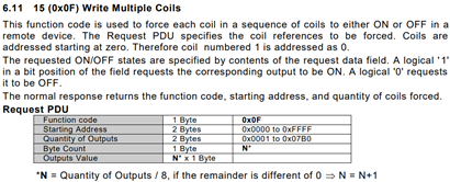
 Hi! So, I am writing ASP Core 2 project and one of the components is communicating with Unitronics V130 unit (as a Modbus Slave). Since provided .NET Driver library is not portable to ASP Core I need to implement this communication with Modbus. I have limited experience with Modbus protocols but I have used some basic functions in the past – mostly reading Registers and Coils. Just to sample some data. I used python library modbus_tk for this purpose. Using Modbus gives me options for adding more optional hardware down the line. After reviewing some libraries supporting Core I selected library Modbus https://github.com/AndreasAmMueller/Modbus made by AndreasAmMueller, written in C# as Net Standard 2.0 library. I started testing this library by communicating over Modbus TCP/IP with V130 PLC. I got mixed results. - namely "Write Multiple Coils " or "Force Coils " (Function code 15) does not work correctly. So. Modbus read functions all work great, these are: Read Coils (Function code 01) Read Holding Registers (Function code 03) Out of write functions these work great too: Write Multiple Registers (Function code 16) – named “#16 Preset Holding Registers” in VisiLogic help files Write Single Coil (Function code 05) – not referenced in Unitronics (VisiLogic) help files under “Slave Addressing” Write Single Register (Function code 06) - not referenced in Unitronics (VisiLogic) help files under “Slave Addressing” These functions are documented in help files of VisiLogic at “Slave Addressing” topic (where address offsets are defined). Now, function that does not work (at least with V130) is: Write Multiple Coils (Function code 15) – named “#15 Force Coils” in VisiLogic help files This function takes in “n” sequential bit values (“coils”) and a “starting address”. Then it writes these values in slave (in my case V130 device), starting at “start address” and for “n” values. It never sets coils to provided values. But it does set provided coils (addresses) just not to provided values. Meaning, if I want to set 16 coils (lets say some Memory Bits – MB) to 1, only some 8 coils would be set to 1, other 8 coils would be set to 0. It appears that only some byte is set to provided values (but that varies with number of provided addresses/values). Let me repeat again – all provided addresses are written to, just not the values that are provided. Interesting thing is that even if I provide only “true” (1) values, somehow “false” (0) is written to address. AFAIK if I provide only “false” values, no “true” value is written to address. Let’s see what is sent to PLC in next section Modbus implementation on PLC? I suppose Unitronics PLC Modbus implementation is compliant to Modbus specifications and implementation guides, defined by http://www.modbus.org/specs.php (I don’t know, but I would hope). As such Modbus TCP/IP ADU (Application Data Unit) should be implemented as defined in http://www.modbus.org/docs/Modbus_Messaging_Implementation_Guide_V1_0a.pdf and Modbus PDU (Protocol Data Unit) as defined in http://www.modbus.org/docs/Modbus_Application_Protocol_V1_1b3.pdf. This is nicely presented in image bellow – Modbus ADU (MBAP Header + MODBUS request). Here request is made for reading register #5 in remote server (page 22/46 from Application Protocol document): There are 6 bytes of MBAP Header, followed by “length – 1” bytes of MODBUS request (we must subtract 1 byte for Unit identifier, which is included in “length”). In example above there are 5 bytes of Modbus request that makes “length” equal 6. Function “Write Multiple Coils (code 15)” Modbus request is defined in Messaging Implementation Guide at page 29/50: This block is inserted at MOBUS request field in Modbus ADU, presented above. It takes 1 byte to describe the function code, 2 bytes for starting address, 2 bytes for quantities of values (number of “coils” we want to write), 1 byte for number of bytes and finally N Bytes for associated values. Simple test For simple test I am going to use function “Write Multiple Coils (code 15)”, writing 16 (2 bytes in length) “true” (1) values, starting at address 1200, which means Memory Bit (MB) #1200. Device ID is 1. This is Modbus request ADU, which is sent to PLC: It appears that the implementation of Modbus in NET Standard 2.0 library is compliant to Modbus specifications and implementation guides, defined by modbus.org. There is correct MBAP Header and MODBUS request. It provides correct address (1200), number of coils (16) and correct values of coils, which is “true” 1 for all, thus 2 bytes with value of 255. But the result of this operation yields, starting at correct address of 1200: 1, 1, 1, 1, 1, 1, 1, 1, 0, 0, 0, 0, 0, 0, 0, 0. We were hoping for all 1. I doubt its wrong implementation in the library, I have checked many requests against specifications from modbus.org and all seem to comply. Ofc the working functions (Read Coils) etc. all comply to modbus.org specifications and yield correct results. Only “Write Multiple Coils (code 15)” function yields wrong results and is there any chance that its not implemented according to modbus.org? Solution/hack that seems to work I found one hack that seems to work (at least with V130 PLC). But I wouldn’t recommend to use it until there is conformation that this hack does not cause some unwanted consequences. Here goes, it appears that appending one (dummy) byte (of arbitrary value) before bytes that represents values (in the above case [12] and [13] bytes) somehow causes the function to work and we can update Length byte [5]. But it seems that updating Length does not have any effect, it works regardless (need to test that more rigorously). New (working) request would look like this, with added dummy byte: As you can see there is added dummy byte at [12] and length updated to 9. Result of this operation yields correct state - all 16 coils MBs are set correctly. This seems to works with any combination of values and number of coils. But this hack is untested, I don’t know if this command is really contained to just defined addresses or does it write all over the memory. I tested this only for some addresses beyond defined range by manually setting values via VisiLogic “online mode". More importantly, why does this hack work? Or even more, why “normal” Write Multiple Coils (code 15) does not work? Is this V130 specific? Any help appreciated! Best Regards! PS: To add, I did change "MODBUS: SCAN_EX" block to SCAN and SCAN_32 - nothing worked. Now I left it with "MODBUS: SCAN" block to support "older working applications" as stated in help files of VisiLogic.


-
Dear sir, I'm trying to communicate tcp/ip (Valves)with v700 unitronics.but communication not yet done pls provide solution to resolve.I have attached ladder for your ref

-
 Hi all, I have hit a roadblock and am asking for guidance. I have a V350 with an Ethernet module connected to a wireless gateway (RV50). The RV50 uses Modbus (socket 2, port 502) to connect to the PLC and port forwarding to allow remote communication (socket 1, port 20256). This communication is great and has been successful for several months. My challenge begins when we want to control the outputs on a separate wireless gateway (GX450) with AT commands from this PLC by using the Protocol TCP/IP Function. The catch is that the GX450 will be in a remote destination and we will not be able to use serial communication. I have configured and initialized socket 0 to use Protocol TCP/IP on port 20255, SB 142 and SB 143 come on, but SB 147 does not. The static IP of my GX450 is 68.25.107.225 and I'm not sure what my remote port # would be (MI1007). I have attached my file and the rungs are under Protocol TCP IP Test except for the Sock Config under Main Routine. 1.) Does this sound possible or is there an easier way? 2.) Has anyone done something like this and could offer some insight? Note: We are using the Sprint network for both the RV50 and the GX450 and have been told by Sprint that they do not offer SMS messaging on the GX450. This is the initial route I wanted to take. Thanks, Josh Goen V350 TR20 Mnet-4-30-18.vlp
 -
 My end goal is to send data over ethernet using the TCP/IP protocol to a raspberry pi. I already have the pi coded in python to look for a connection to its ip on a socket that I bound to it. My problem I believe is within the V570 PLC programming logic itself. I have initialized the card with ip 10.1.10.160 and my laptop with ip 10.1.10.100. Those two communicate correctly over ethernet. My pi is at ip 10.1.10.166. The pi is bound to a socket and currently waiting for something to connect to it on port 8888. I initialized socket 3 on the PLC as a Master on port 20257 and set the name to 'raspberryplc' Like I mentioned, the PLC and PC communicate correctly over ethernet. Lastly I have the TCP/IP config block which is initialized to socket 3 at ip 10.1.10.166 on port 8888. I then use SB142, 146 and 150 to check if I'm ready to attempt a connection, all still good and expected. I get a status 0 from the TCP/IP config block which signifies an all set response. I then have my TCP/IP CONNECT block set to Socket 3 to remote ip 10.1.10.166 on port 8888. At this point SB150 never goes high and I don't establish a connection. I can see something must be happening as when I stop and start the connection attempt on the PLC side, I can see the ethernet lights blinking on the raspberry pi. Thoughts? Either I'm missing something or it's correct but my raspberry pi is messed up. Thank you for any help anyone can offer.
-
OK, I am stuck, and to be honest I have no idea why I am stuck. All I want to do is request a web page from a web server. Specifically, I have created a PHP page that will return the string "OK" when called. I am using this page for the PLC to report that it has an error. Inside the PHP, I will use the parameters to identify the PLC and the error. This should be easy, Right? I have configured my port and my TCP/IP configuration to socket 3, port 504. I issue a TCP/IP connect to the server (IP is correct, port is 80), and it appears to connect. I then issue a TCP/IP Send to send the GET /url/r/nHost: <hostname>/r/n/r/n/r/n. And that is where I am stuck. It does not appear that the message is sent to the sever. In fact, my web server never "sees" the request. Does anyone have any idea how to issue a url request to a web server? I do not even care about what I get back, I just want to call the page. Any help is greatly welcome. Thank you in advance. Tim J.
-
 I have been tasked with developing a centralized server that will communicate with many Samba PLCs around the world. Specifically, I need to ensure that the server can contact any PLC and 1) get a copy of the current values or 2) instruct the PLC to change a value. I want to ensure that the PLCs only communicate with the server, no other computers. The data itself is not considered secret, so the fact that VisiLogic does not appear to offer encryption is not a problem. But, it is critical that only the server be allowed to update PLC values. It is simply unacceptable that another person could connect and update values, even if it would take quite the effort to accomplish that goal. Is there any way to ensure that the PLC's will only respond to requests/instructions from our centralized server? If I send a password, as a message, that password would not be encrypted, so others could see and use it. Is there anyway to securely connect to a Samba PLC, using VisiLogic? The server will know the PLC name and the IP Address, but once again, this would be transmitted unencrypted. Is there a way to program the PLC's to only accept connections from certain IP Addresses? In summary, I want to ensure that the PLCs will listen for communication from our server, they will send current values when requested, they will update their values when told, and they will ignore any requests from others. Is this possible? Any suggestions are greatly appreciated.
 -
 I'm trying to connect my PC with a Unitronics PLC. I would like to use Modbus over TCP/IP for this purpose. This is the first step in my project. Later on I would like to connect it to a Rabbit Wolf (BL2600) to exchange I/O. I first want to connect the Unitornics PLC to my laptop to get a decent understanding of the Modbus TCP/IP protocol used by Unitronics. At the moment I'm already stuck, so I hope that someone could help me. I did read the documentation about Modbus Application Protocol on: http://www.modbus.org/docs/Modbus_Application_Protocol_V1_1b.pdf I'm using the Unitronics example code: V280_Ethernet_TCP_MODBUS_IP_Master (without any changes) I used the Vellamod tool to connect and send data: http://www.tuomio.fi/vellamod/index.htm (I'm running windows 8, so I have some problems with other tools and this one seems to work nice) I'm using Wireshark to inspect the TCP/IP traffic. However, I'm now in the current situation. The laptop connects, but I don't get any response. I connect to 192.168.192.5 on port 502. My laptop is set to 192.168.192.10 (subnetmask 255.255.255.0, gateway 192.168.192.254) I try to send the following (see attachment for a printscreen): byte 0: transaction identifier = 0 byte 1: transaction identifier = 0 byte 2: protocol identifier = 0 byte 3: protocol identifier = 0 byte 4: length field (upper byte) = 0 byte 5: length field (lower byte) = 2 byte 6: unit identifier = 255 byte 7: MODBUS function code = tried 3 (Read Holding Registers) and 4 (Read Input Register) byte 8: 00 byte 9: 26 (I try to read MI 38) When I than inspect the transmission with WireShark, I get the following Source: 192.168.192.10 Destionation: 192.168.192.5 Protocol: Modbus/TCP Length: 64 Info: Query: Trans: 0; Unit: 255, Func: 3: Read Holding Registers[Malformed Packet][Malformed Packet] When I set: byte 5: length field (lower byte) = 6 I get no error, but I also receive nothing with the Vellamod tool. According to Wireshark I receive the following: First Source: 192.168.192.5 Destionation: 192.168.192.10 Protocol: TCP Length: 60 Info: asa-appl-proto > 49933 [ACK] Seq=1 Ack=325 Win=1024 Len=0 Followed by Source: 192.168.192.10 Destionation: 192.168.192.5 Protocol: TCP Length: 64 Info: [TCP segment of a reassembled PDU] And finally Source: 192.168.192.5 Destionation: 192.168.192.10 Protocol: TCP Length: 60 Info: asa-appl-proto > 49933 [ACK] Seq=1 Ack=335 Win=1024 Len=0 On the PLC HMI nothing is changing (Socket 3 total transmits: 0;Socket 3 total reiveces: 0) The only strange thing that I can see is that it (Unitronics) seems to use destination port 49933, but I don't know whether this is wrong or right. Hopefully someone can help me. Visual basic code, would also be more than welcome. Kind regards, Peter
-
 Hi there, I am having some trouble reading variable length numbers in a "Protocol TCP/IP Scan" block. We are receiving a message of the form "-9999999999.999 [Counts16Bit]". Messages can be positive or negative and can contain a variable number of digits, so "9.999 [Counts16Bit]" is also a valid message. I am able to successfully use the scan block with fixed length messages. If I construct a message like "111 [Counts16Bit]0A" where the numeric variable is "Decimal ASCII: Fixed Length", Vector Length = 1, Length = 3, "No Prefix", I can receive any 3 digit number successfully. If I change the numeric variable to "Negative Only (-)", I can only receive messages with a "-" sign. I would expect to be able to receive 3 digit messages with or without a "-" sign. If I construct a message like "1 [Counts16Bit]0A" where the numeric variable is "Decimal ASCII: No Fixed Length", "No Prefix", I do not receive any messages, even ones with a single digit. Is there something I am missing. I would really appreciate any suggestions.


