Search the Community
Showing results for tags 'RS232'.
Found 21 results
-

Non-standard use of RS 232 port as.... discrete PLC input.
kratmel posted a topic in Tips and Tricks
While upgrading the control system of the parts washer, I ran into a supply problem now called "chip shortage". In general, there was a remote control box with V570 panel and a control cabinet at a distance of 20 m, in which the EX D16A3-TO16 extension module is located. It uses all inputs and outputs for the machine's needs. The start of the automatic cycle had to be done with protected hermetic buttons on the remote control box near the panel (this requirement is dictated by the abrasive that is on the parts that are loaded into the parts washer, this abrasive on the gloves of the workers can quickly destroy the touch panel). However, the V570 requires a snap-in module to connect two buttons. And this particular module was not available... The solution was found and the system is already working. Now in more detail. Two panel com ports (RS232) are used as two discrete inputs. Below is the button connection diagram and a piece of ladder code that explains the idea. The machine is already in operation. P.S. I will have to wait for the snap-in for some time and then connect everything as originally planned.

-
 Hi! I'm new to this forum so please be patient with me. I'm trying to automate a cable cutter that uses Unitronix M90. I want it to load a certain length and quantity when I scan a barcode. Have any of you sirs connected M90's RS232 to the serial of Raspberry Pi? Is there a set of code to send to the M90 for it to be able to communicate? Sorry the machine is always running and I need data before I can try and test.
 -
 I am trying to receive data from an instrument. The data stream is a series of binary numbers. The help file for the Protocol FB says that it can receive a variable as a binary number. However, in practice this does not seem to be the case. Can a V700 PLC receive a binary number and save it into an MI ? again using the protocol scan function I do not see how this is possible. Thanks for any help with this. Bill
 -
 Hi! I have a communication developed with v230, v350... With visiologic, And now i have to do the same applications but in Unilogic environment, but i'm experiencing some dificult by the new plataform and new tools, theese applicatins was maded to "send and receive" messages through Rs232, to send messages i already have "some sucess", but it's not working to receive msg, i need to receive and shows the value received at the hmi in a decimal format, visiologic com_ok_2019 - Copy.vlp RS232_SEND_PROTOCOL_MULTIPLE_WORKING_RS232 - Copy.ulpr If anyone could help me I aprecciate a lot.
 -
Im having issues with getting communication from a Unistream 7 to a syringe pump through a usb to RS232 cable. I am trying to use the message composer to send commands over but have not been successful. The brand of pump I am using is Chemyx (https://www.chemyx.com/support/knowledge-base/programming-and-computer-control/serial-rs232-commands/) The cable is good as I can take that same cable, connect to a PC, connect thru putty thru its COM port, and type commands without an issue. I enabled "USB for Serial Communication" under the PLC communication tab only changing the Baud rate to 38400 and message composer was setup with text strings following Unistreams guide but I was not successful in getting communication (http://support.unitronics.com/index.php?/selfhelp/view-article/unistream-and-communication-with-3rd-party-devices). Any ideas as to why I cant send a "start" string or "stop" string? Also does it matter if I use USB 1 or 2? Would a UAC-01RS2 serial module help? I am using the microusb port to connect to the PLC if that matters Thanks
-
Hi all, I want to use a V700 and a device which also use RS232 connection protocol. There are some datas that should be read and controlling of ON/OFF status of the device. However, this will be the first time that I will use RS232 communication. How can I program this? For example, there is a command that I need to use below. I need to read those values and seperate the temperatures to different MI's. I believe I succeed to initialise communication port but not really sure. $TEA: Read all temperatures Command with checksum and carriage return = $TEAA4B9<cr> Response: $TEA,T1,T2,T3,T4,<crc-16><cr>
-
 I have multiple devices such as printers(2) and scanners(2) that I want to communicate to using only 1 COM port in V1040 PLC. Printers and scanners support RS232/RS485 protocols. Can someone suggest on how can I achieve this? I looked at options with Modbus protocols, but I didn't understand how can I assign network id's to my printers and scanners. If I am required to have any additional hardware, please suggest.
 -
 Hi. I have a Unitronics JZ20-R16 (Jazz2) controller I’ve programmed to run a simple air ventilation system in my house (The thing is running great btw.). I also have a self made Arduino based data logger (I use it to monitor and log my energy consumption, temperature, etc.) I’m not building those things or mass producing, Arduino electronics is my hobby - I just use it to stay sharp. So I decided to cross-integrate my air vent. Controller with my data logging unit (I want to see the status of my air vent. Controller unit on Arduino). So for starters the task is to simply send a 16bit int to Arduino and receive another 16bit int from the Arduino. The communication protocol of the choice was MODBUS through RS232 interface (as I already have MJ20-PRG; MJ20-CB200 and a MJ10-22-CS10). I’ve decided to use JZ20-R16 as a Master (Arduino as a Slave) in a 9600 baud 8N1 configuration (default for JZ20-R16). For Arduino’s RS232 interface I’ve used TTL-RS232 converter (MAX3232 based) : Experiment 1: In order to see if the Arduino’s MODBUS feature is working I’ve connected Arduino to my PC using the given connector and a RS232-USB converter. Arduino was configured as a slave and ModbusPoll software (http://www.modbustools.com/modbus_poll.html) simulated a master. I was able to both read a holding register from Arduino (03) and also write a register (06). Those are the desired options. Experiment 2: In order to see how MODBUS is working on JZ20-R16 I’ve hooked it up to my PC using my MJ20-PRG; MJ20-CB200 and a MJ10-22-CS10 later connected to RS232-USB converter. I’ve uploaded a program (by pressing buttons 1 and 4 I send an int or correspondingly request an int from slave): (see in uploaded files) It make the JZ20-R16 work as a Modbus master on a RS232 interface. In order to simulate a slave I’ve used ModbusSlave software (http://www.modbustools.com/modbus_slave.html) . Once again, the combination worked perfectly. Once again all the required commands worked. Here’s the photo of my hookup: Then I’ve noticed a possible cause for future problems : lines 4 and 7 of my MJ10-22-CS10 are actually used in this communication. It turned out that the RS232 communication with JZ20-R16 require 6 wire communication instead of 3 wire communication I’ve expected from RS232 interface. Due to the requirement of RTS and DTR signals! I’ve turned on my scope and actually saw those signals on pins 4 and 7 of MJ10-22-CS10 connector going high after the “handshaking” with my slave simulator was done. With PC USB disconnected: PC USB Connected: MudbusSlave after “handshaking”: Successful communication: CH3/4 are the DTR and DTS signals correspondingly. At this point I’ve realizes that sue to those signals I would not be able to connect my Unitronics to my Arduino, as the TTL-RS232 connector simply do not support DTR and DTS signals. So after hooking up my Arduino to Unitronics I see the following on the scope: Both DTR and DTS signals are on 0 instead of HIGH, which prevents the JZ20-R16 from accessing the modbus. The questions: Is there any chance to make JZ20-R16 communicate over RS232 without use of DTR/DTS signals? Is there an option to tweak those signals (connecting them to +5V permanently) Use of other TTL-RS232 converter? Any other way to make Arduino and JZ20-R16 communicate over RS232 interface using MODBUS Thank you for the patience. samplemodbusmaster232.U90
 -
 Good morning. I am trying to print messages using the send protocol from a Vision120 to an epson lx350 dot matrix printer. I have the Com Init command and the protocol config command setup. I have it wired up correctly (I believe) from the RJ11 to RJ45 to the DB25 adapter to plug into the printer. This system has worked in the past, I inherited the project from a customer who's controls engineer left, and now I'm stuck on getting the printer to work. I have downloaded the program and HMI config and they are working fine. Does anyone have experience in something similar to this? Is there something on the printer side I have to do? Let's assume that I have the communication wiring 100% correct. I still have to verify that again in the morning. Thanks a lot, Adam McCormick
 -
 Hi All - I am working to connect a barcode reader to a Vision 120 PLC via RS232. I have two barcode readers on hand - a Motorola Symbol LS4278 (which reads 1D and 2D codes), and a 1D-only Royal PS700-LSR. Both readers are set up the same way - serial cable with external power input into the scanner, connected to the PLC by a DB9 to RJ45 adapter. When connected to a Serial-to-USB converter to the computer, both scanners send the same data to the Serial Terminal (I am using Hercules). But when connected to the PLC, the Royal scanner data is read as expected, but nothing happens when scanning codes with the Symbol scanner. On the PLC, the Session Complete bit is never set by the Protocol Scan block so none of the other processing is triggered when the Symbol scanner is connected. With the Royal scanner, each scan flips the Session Complete bit, and data is copied and formatted correctly. When the scanners are connected to the computer, I see the exact same hex characters in Hercules from both scanners. PLC program attached. I have tried and confirmed various serial communication settings (baud rate, STX/ETX chars, handshaking, etc.) to match between the scanner and the PLC, and I have worked through the suggestions in this thread: Can anyone suggest what the difference between the two readers might be? I need to make the Symbol reader work since the system will read 2D barcodes. Thanks, Doug Davies 120-barcode-scanner2.vlp
 -
Hi! How to change Unistream UAC-01RS2 module RS232 serial port communication parameters within ladder function? Connected serial device (Kamstrup Multical M66 type energy meter) use different baudrate for Rx and Tx communication. I need to swap Unistream serial port baudrate between 300 for Rx and 1200 for Tx to get data from energy meter. Also Unilogic serial port configuration allow minimum baudrate only 1200, but there is a need for 300! In Visilogic it is simple, there is a "COM Init" function block for this purpose, that i can use within ladder. How to resolve it within Unilogic ladder??? This is a major problem and need urgent resolving! "This is not possible" is not the right answer!
-
Good Morning I have not written my program yet, but I want to be able to communicate a string from my new Unistream to a RS232 device, in fact a Hitachi Printer I have successfully done this with a Vision PLC, but now all of my inbuilt FB's have gone with Unistream, and I am struggling I have added a Com device to the unit, and configured it ( I think) I cannot see however to set the pre amble and post amble for my strings what I want to do is On the HMI have a string called lot and another string called Julian Date I then want to be able to send those strings to the Hitachi with the correct coding for the machine They will be sent at one time so the string to send will look lile STX [DLE] 1 (LOT) [DLE] 2 (JULIAN) ETX I looked in the help files and didnt see anything there so I am now asking for help here Thanks in advance
-
update: 12-10-16 I take that back, I failed after two weeks of trying every conceivable configuration to implement a complete working model of serial MODBUS with read holding register and write coils exchanges to four vision slaves over RS232 radio modems. Has anyone out here successfully setup a Unistream master to a Vision slave, serial, 232 over modems (RF), read registers (more than one) and write coils; without errors? For example sequentially reading five 16 bit integers and in next line of periodic slave table writing a 10 bit array of coils (or a single 16 bit write register)? 9600, 1, none, must do four RHR #3 and write coils (10 but array) to four slaves all in a cyclical (periodic) fashion. I can't make it work to save my life. I really need to know if anyone else has a working UniStream to Vision serial modbus system working as expected! Now IF you only do read holding registers or only write coils THEN it works fine. However when stacking different MODBUS operations into a single slave table in periodic mode one or the other function takes precendence over it's neighbor. I had the latest version of UniLogic and UniStream firmware as of December 1st 2016. Had to table the UniStream and go to a Vision 1210 to complete my project. However I desperately want to use the UniStream as an MTU/controller in my project.
-
 Hi, I 'm new to samba and Visulogic programming, and I'm having some problems to use the samba sm35-j-t20 serial port to send data into a chinese printer(csn-a2-r), it uses rs232... I initialize the the com with the printer parameters and I configured an protocol, but when I try to send the messages something goes wrong, The data is not sed correctly, it appears ramdom stuff in the printer. obs.: the printer is 12vdc so I hacked it with a lm7812 to be able to use it with the same power supply. Someone have done something similar and/or can help please? here is the link for the printer and i'm attaching the code for the samba. https://cdn-shop.adafruit.com/datasheets/CSN-A2+User+Manual.pdf giga de testes com impressora.vlp
 -
Hi I have two old units but i haven't got original cable. I dont know if they work good so i tried to connect to them with my pl2303 rs232 to USB converter and an rj11 cable. Tried it on Windows 8.1 64bit and Windows 7 64bit. Evertime it say that it can't synchronise with PLC. I use proper COM and got good drivers and good settings.
-
Hi everybody, Greetings to all, another newbie here... Having some issues on getting Modbus RTU messages to work on JAZZ PLC. My setup: 1) JZ20-R16 PLC with MJ20-PRG adapter (?) plugged in it. I'm using MJ20-CB200 cable (RJ11 plugs on both ends) and MJ10--22-CS10 adaptor (DB9 female connector). Using this gear I can query the PLC with modbus RTU messages over RS232 serial line. Serial line settings I use: 9600bps, 8(data bits), none(parity), 1(stop bits) 2) Gemalto modem (BGS5T) as a modbus master. It has DB9 female connector on it as well. 3) Serial to USB converter cable for serial communication verification. A bit of context: while using serial-to-usb cable I can't query PLC all the time. That means, *sometimes* I can query it successfully, but after disconnecting and messing around a bit I cannot query PLC any more. Unplugging USB-to-serial and reconnecting helps, so I assume it's kinda converter drivers/whatever issues so not a big deal here, just a note. So using this cable I can verify, that PLC *can* (though not always I would expect) respond to Modbus RTU messages properly using defined settings above. I have couple of Modbus master simulation programs and strangely enough only one of them can query the PLC successfully. Real problem: I have written peace of software for BGS5T to act as a modbus tcp/ip to modbus rtu gateway. I can verify that this gateway works by three methods: 1) run modbus slave simulator on a PC, connect gateway over serial line to PC (same usb-to-serial cable used here) and query PC slave simulator over that modem acting as a gateway. Everything's just fine. 2) I can connect to the terminal program on a PC and verify that sent message to serial line is valid modbus RTU message: 0x01 0x03 0x00 0x02 0x00 0x01 0x25 0xCA : (from left to right hexadecimal values) 1) device ID (1 byte) 2) function code (1 byte) 3) start address (2 bytes) 4) register count to read (2 bytes) 5) CRC (MSB) 6) CRC (LSB) 3) I have made "sniffing" rs232 cable and I can listen on messages being set to PLC or being received from PLC (depends on wire I'm hooking to). I can verify that exactly the message defined above is sent to PLC using serial settings mentioned above. PLC does not respond with anything. Absolute silence.... I used 3 wire connections (Tx, Rx, GND), used null-modem configuration for both modem and PLC, nothing helps. JAZZ PLC is silent for those messages. What could be wrong here? Voltage levels does not match..? handshaking is mandatory on JAZZ PLCs..? I'm completelly out of ideas to try out, cannot sleep normally over a week now... I don't know much details about serial line physical implementation, so feel unsure in this topic. Please help. Regards from LTU
-
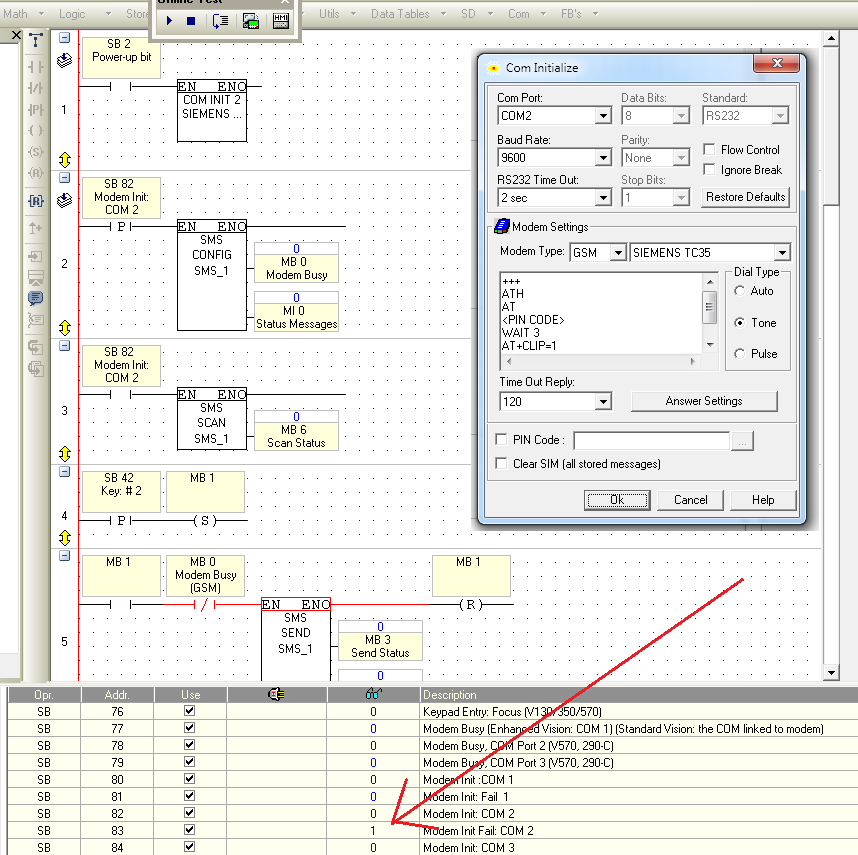
 When I connect TC35i modem to PC via USB-to-RS232 converter everything works greate. Doing "Prepare PLC-side modem" in Modem Services in VisiLogic OPLC IDE result in connection and success. Making a test dial from Modem Services also results in success. But when I connect my PLC (it is V560) with the modem using a 4-wire RJ11 programming cable (ended with MJ10-22-CS25 and simple Male-to-Male adapter) then the Modem Init fails and SB 83 bit become 1 (SB 83 is Modem Init Fail for COM 2). I suppose that something wrong is with the cable. How am I supposed to connect V560 to TC35i? Thanks for help...
-
 Am using Red Lion display, model PAX2D, with an option card for RS232, and want use Modbus RTU to display values from a V350. I can get successful comm. by connecting RXD from display to RXD(pin 3) on V350, and TXD to TXD(pin 4) with no ground. As soon as common (pins 2 or 5 on V350) are connected to RS232 common on display, comm. halts. By wiring as above, I can read values from registers in the display, but they seem to be random numbers, not anywhere close to what they should be. For instance when reading register 40483(display baud rate), a value of 8960 is returned no matter what the baud rate is actually set at, and I would be expecting to see a number from 0 to 5 for the 5 baud rates available on the display. PAX2D display manual: http://www.redlion.net/Products/Groups/Counter/Rate/PAX2D/Docs/04038.pdf PAX2D Modbus table: http://www.redlion.net/Products/Groups/Counter/Rate/PAX2D/Docs/04045.pdf PAX2D RS232 option card manual: http://www.redlion.net/Products/Groups/PAXOptionCards/PAXCDC1,2/Docs/12018.pdf V350 program: https://www.dropbox.com/s/86hmdjtqg0qdkqd/Test%20Display.vlp I talked with Red Lion tech support to make sure display setup is correct. Appreciate any help!
 -
 Good Morning, This has driven me to drink, well it seemed like a good excuse! I am trying to connect a Microscan HS-1 Barcode scanner through RS232 to Com Port 2 of a V120 PLC From what I can see I have everything set right, but when I trigger the hand held scanner the information that I have scanned does not appear to be sent to the PLC I have all my Baud rates, pre ambles and post ambles set right in the scanner, I feel if I have everything right, but I just cant get the flow of information. I have attached the program and am looking for someone brighter than me to see where my dumb *** has gone wrong, or at least point me in the right direction! One thing I am not 100% sure about is the cable I am using to connect the scanner to PLC, I am using a spare programming cable that came with the PLC..Is this my issue? smooth4.vlp
 -
Good evening I have written a program for a barcode scanner that reads a barcode and parses the info to the screen, and then communicates it to a printer I do however have a couple of issues 1) If I plug the scanner into the port of the V120 it doesnt work, however I think that must just be me, as I downloaded a program called termite and plugged in the PLC to one port and the scanner to another, set my ports to forward in the program from the scanner to the PLC and it works. The major problems that I am facing is that unless I switch screens the HMI does not update, cant work out how to do that.. any thoughts The next problem is that if the first barcode I scan is 20 characters long and the next is 15 then the last 5 characters do not clear out, but stay with the new scan, this I dont understand so if anyone has some ideas I would love to hear them Thanks
-
Hello, I have a .net application that connects to a 570 via RS-232 using System.IO.Ports.SerialPort. Normally, it will connect. However, when playing with different baud rates, it sometimes does not connect until I connect the same PC with any Unitronics software (Visilogic or Remote Operator). My question is this: With VIsilogic, it appears that you can define the baud rate to anything in the connection properties and it always connects. How does the controller adapt accordingly? I think "out of the box", the rate is set to 115200. If I change my application to 57600, it failes to connect. But, if I connect using Visilogic @ 57600 it works. I go back to my application and then it works. I am trying to determine what Visilogic is doing that I am not. My connection looks like this: // Connect to the PLC try { string comPort = Properties.Settings.Default.CommPort; int comBdRate = Properties.Settings.Default.CommBdRate; int comTimeOut = Properties.Settings.Default.CommTimeOut; _serialPort.PortName = comPort; _serialPort.BaudRate = comBdRate; _serialPort.DataBits = 8; _serialPort.Parity = Parity.None; _serialPort.Handshake = Handshake.None; _serialPort.ReadTimeout = comTimeOut; _serialPort.NewLine = "\r"; _serialPort.Open(); } catch (Exception) { // Disconnect from the PLC _serialPort.Close(); } Once this executes, I begin sending PCOM commands: try { // Send the message out the serial port. _serialPort.DiscardInBuffer(); _serialPort.WriteLine(message); // Verify the message was received, catch the timeout string response = _serialPort.ReadTo("/A00SBF5"); if (response == "/A00SBF5") { //do nothing, success!! } } catch (Exception) { _connectionLost = true; _serialPort.Close(); return -1; } The _serialPort.ReadTo() catches the timeout (default 1 sec). When that occurs, we assume we lost the connection. Is there something I should be doing to prime the port first? Thanks!