Search the Community
Showing results for tags 'V130'.
-
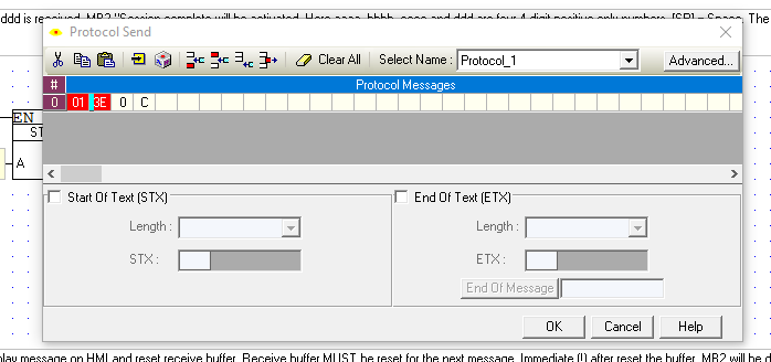
 Hey all, I'm new programmer in visilogic IDE and my device is v130-33-TA24. My program purpose is to communicate via RS485, 9 bits to receive data from device. I initialized COM1 and set protocol Send&Scan by the connected device protocol. but nothing is show on screen(I've linked the received data into number on screen). I add some pictures for description. I'll be glad for help


-
 Hello, I would be grateful for some help with configuring the TCP/IP connection of the V130 controller. I have the V100-17-ET2 ethernet card in it and I did some initial attempts. So far I can see in the system bits that: SB 141 - card exists = 1 SB 142 - card initialized = 1 SB 143 - socket 0 initialized = 1 (that's the one I'm trying to use) SB 151 - ethernet status: link = 1 SB 153 - ethernet status: rate, 100 mbps = 1 For now I'm testing this right next to my PC, plugged to my home router and I'm trying to get anything to work. Right off the bat I see no DHCP, the card init block just asks me for a static IP. I could configure my router with a static IP for it, but I need the MAC address of the card - which turns out to be surprisingly hard to find. Nothing on the box, nothing in the box, nothing in the VisiLogic documentation that I could find. I found the (undocumented) SDW 22 and SDW 23 operands labeled as MAC Address, but I'm not completely sure how to convert them to a MAC address. What I tried so far is: SDW 22 = 573548024 = (hex) 22 2F A5 F8 SDW 23 = 13 = (hex) D MAC has 6 bytes, so I'm assuming that "D" from SDW 23 actually means "00 0D". I still don't know in which order the operands and bytes should be used to get the MAC address. As things are I'm struggling to do a simple ping, not to mention implementing the FTP operations and printing that I need to do. Like I said in the beginning - any hints/help would be appreciated.
 -
Hi, I'm using V130 to control school shedules and some building automations. They recently added "Master clock", device that sync it own internal time via GPS. It has several communication protocols, but the only one that is maybe usable for me is SNMP. I must admit, this is the first time I met with this kind of protocol, so I need some tips from you guys. Namely, idea was that V130 internal clock is syncronized with the Master clock, so I thought that I can use SNMP. My question is, does that can be done? I mean, it looks theoreticaly possible to me - to store MI that I receive from Master clock, and store it to SI (35,36,37)? If someone is willing to take a look, model of Master clock is attached in PDF. It is Rack version. Thank you in advance for any help. 643331_Modular_master_clock_Sigma_Mod.pdf
-

V130-33-TR34 HSO
tbalogh posted a topic in Vision & Samba PLC + HMI Controllers & VisiLogic Software
Hi, I'm a new user and I've been trying to get a PTO pulse signal from one of the high speed outputs of my V130-33-TR34 to send to a stepper motor driver. I just got the PLC so it's set to default jumper settings. I pretty much followed the webinar on the Unitronics site and I'm pretty sure I did the wiring right (pin 1 on the transistor outputs to driver, pin 5 to PLC ground). Hooked it up to an oscilloscope and I don't get anything out. When I run the PTO move command, it turns the MB on for "PTO Move Success." Tried going into the HW Configuration and trying to get a PWM signal out by setting up one of those and initializing Frequency to 500, Duty cycle to 500 (50%), and then downloading a program with just ---|SB2|---(MB0)(S) where MB0 is the PWM "Run Bit" and still nothing. Anybody see something simple I overlooked or something I did wrong? If not, any ideas what might be going wrong? Thanks in advance -
 hi all I try to connect more then one master to my slave(PLC v130) with MODBUS TCP , the masters need to work simultaneously. can someone send my example how to do it?
 -
 Hi, I have a working code downloaded to a V130-33-R2 model that uses an analog input. This works perfect, however after some years the hmi screen does not work properly anymore. I tried to order that same part number but apparently Unitronics does not sell that PLC anymore. Therefore, I bought a similar one (V130-33-TR20) , however when I download the code to this new plc, the analog input does not read anything anymore. I even changed the HW configuration to the right model. Am I missing something else I need to change in the configurations to make this code work? Thanks,
 -
 Greeting, I want to ask whether V130 can accept 2 type of analogue input if im using external analogue module or not. 2 (0-10v) analogue signal to PLC and another 2 (4-20 mA) analogue signal to external analogue module. Is it possible with V130 PLC
 -
 Hello! I am trying to create a program that will extend a cylinder for 10 seconds with valve 1, retract after the 10s and have a running count of the cycle after it is retracted. While doing this, I want valve 2 to ‘dump' the air after valve 1 has been on for 5 seconds so there is no pneumatic force in the extend position after the initial 5 seconds of valve 1 opening. Is this possible? Any insights would be greatly appreciated! I am using VisiLogic to write my program and V130-33-T2 hardware. Please advise!
 -
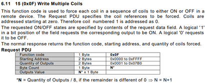
 Hi! So, I am writing ASP Core 2 project and one of the components is communicating with Unitronics V130 unit (as a Modbus Slave). Since provided .NET Driver library is not portable to ASP Core I need to implement this communication with Modbus. I have limited experience with Modbus protocols but I have used some basic functions in the past – mostly reading Registers and Coils. Just to sample some data. I used python library modbus_tk for this purpose. Using Modbus gives me options for adding more optional hardware down the line. After reviewing some libraries supporting Core I selected library Modbus https://github.com/AndreasAmMueller/Modbus made by AndreasAmMueller, written in C# as Net Standard 2.0 library. I started testing this library by communicating over Modbus TCP/IP with V130 PLC. I got mixed results. - namely "Write Multiple Coils " or "Force Coils " (Function code 15) does not work correctly. So. Modbus read functions all work great, these are: Read Coils (Function code 01) Read Holding Registers (Function code 03) Out of write functions these work great too: Write Multiple Registers (Function code 16) – named “#16 Preset Holding Registers” in VisiLogic help files Write Single Coil (Function code 05) – not referenced in Unitronics (VisiLogic) help files under “Slave Addressing” Write Single Register (Function code 06) - not referenced in Unitronics (VisiLogic) help files under “Slave Addressing” These functions are documented in help files of VisiLogic at “Slave Addressing” topic (where address offsets are defined). Now, function that does not work (at least with V130) is: Write Multiple Coils (Function code 15) – named “#15 Force Coils” in VisiLogic help files This function takes in “n” sequential bit values (“coils”) and a “starting address”. Then it writes these values in slave (in my case V130 device), starting at “start address” and for “n” values. It never sets coils to provided values. But it does set provided coils (addresses) just not to provided values. Meaning, if I want to set 16 coils (lets say some Memory Bits – MB) to 1, only some 8 coils would be set to 1, other 8 coils would be set to 0. It appears that only some byte is set to provided values (but that varies with number of provided addresses/values). Let me repeat again – all provided addresses are written to, just not the values that are provided. Interesting thing is that even if I provide only “true” (1) values, somehow “false” (0) is written to address. AFAIK if I provide only “false” values, no “true” value is written to address. Let’s see what is sent to PLC in next section Modbus implementation on PLC? I suppose Unitronics PLC Modbus implementation is compliant to Modbus specifications and implementation guides, defined by http://www.modbus.org/specs.php (I don’t know, but I would hope). As such Modbus TCP/IP ADU (Application Data Unit) should be implemented as defined in http://www.modbus.org/docs/Modbus_Messaging_Implementation_Guide_V1_0a.pdf and Modbus PDU (Protocol Data Unit) as defined in http://www.modbus.org/docs/Modbus_Application_Protocol_V1_1b3.pdf. This is nicely presented in image bellow – Modbus ADU (MBAP Header + MODBUS request). Here request is made for reading register #5 in remote server (page 22/46 from Application Protocol document): There are 6 bytes of MBAP Header, followed by “length – 1” bytes of MODBUS request (we must subtract 1 byte for Unit identifier, which is included in “length”). In example above there are 5 bytes of Modbus request that makes “length” equal 6. Function “Write Multiple Coils (code 15)” Modbus request is defined in Messaging Implementation Guide at page 29/50: This block is inserted at MOBUS request field in Modbus ADU, presented above. It takes 1 byte to describe the function code, 2 bytes for starting address, 2 bytes for quantities of values (number of “coils” we want to write), 1 byte for number of bytes and finally N Bytes for associated values. Simple test For simple test I am going to use function “Write Multiple Coils (code 15)”, writing 16 (2 bytes in length) “true” (1) values, starting at address 1200, which means Memory Bit (MB) #1200. Device ID is 1. This is Modbus request ADU, which is sent to PLC: It appears that the implementation of Modbus in NET Standard 2.0 library is compliant to Modbus specifications and implementation guides, defined by modbus.org. There is correct MBAP Header and MODBUS request. It provides correct address (1200), number of coils (16) and correct values of coils, which is “true” 1 for all, thus 2 bytes with value of 255. But the result of this operation yields, starting at correct address of 1200: 1, 1, 1, 1, 1, 1, 1, 1, 0, 0, 0, 0, 0, 0, 0, 0. We were hoping for all 1. I doubt its wrong implementation in the library, I have checked many requests against specifications from modbus.org and all seem to comply. Ofc the working functions (Read Coils) etc. all comply to modbus.org specifications and yield correct results. Only “Write Multiple Coils (code 15)” function yields wrong results and is there any chance that its not implemented according to modbus.org? Solution/hack that seems to work I found one hack that seems to work (at least with V130 PLC). But I wouldn’t recommend to use it until there is conformation that this hack does not cause some unwanted consequences. Here goes, it appears that appending one (dummy) byte (of arbitrary value) before bytes that represents values (in the above case [12] and [13] bytes) somehow causes the function to work and we can update Length byte [5]. But it seems that updating Length does not have any effect, it works regardless (need to test that more rigorously). New (working) request would look like this, with added dummy byte: As you can see there is added dummy byte at [12] and length updated to 9. Result of this operation yields correct state - all 16 coils MBs are set correctly. This seems to works with any combination of values and number of coils. But this hack is untested, I don’t know if this command is really contained to just defined addresses or does it write all over the memory. I tested this only for some addresses beyond defined range by manually setting values via VisiLogic “online mode". More importantly, why does this hack work? Or even more, why “normal” Write Multiple Coils (code 15) does not work? Is this V130 specific? Any help appreciated! Best Regards! PS: To add, I did change "MODBUS: SCAN_EX" block to SCAN and SCAN_32 - nothing worked. Now I left it with "MODBUS: SCAN" block to support "older working applications" as stated in help files of VisiLogic.


-
Hi, (Edit: For convenience, the final solution of this issue is at the end of this first post) I am having problems with ethernet connection on V130 (33-R34) OS 4.4 (31) with V100-17-ET2 ethernet module. Problem is that sometimes (mostly random) connection somehow breaks and I am no longer able to communicate with V130 (using Visilogic) via Ethernet. To be more precise: Ethernet connection sometimes breaks after downloading the project (after RUN command is send). I don't have the data on how the Ethernet behaves when PLC is running for a long time - this project is new and I have been able to test it only for some days. But as for now I have never get disconnection while running "Online Test" mode or while downloading the project (just right after downloading). But while programing V130 and testing the project/program (for the past week or so) I noticed that after downloading the project sometimes Ethernet would work right away but other times wont. This even happens if there are no changes to Power-up setup of Ethernet. There is no difference If I Burn the project or just Download it. It happens when the PLC restarts and it’s about let’s say 80% chance that it will work and 20% that it won’t. Which is really frustrating because I cannot rely on this to be able to program or control the PLC remotely. What usually works to reestablish the connection is to power off and back on the PLC (not great) OR to just un-plug the Ethernet cable, wait a few sec and plug it back in. Sometimes I need to wait ~2sec before plugging it back in and sometimes ~5sec for the connection to work again. My initialization process is presented in attached file. I had shuffled the “PLC NAME”, “TCP/IP” etc. blocks in all combinations and nothing works. Maybe it’s a network thing (but if I recall it correctly I had similar problems when I started using V130 and learn how to use it on my home network, but I shrugged it off as “beginner problems. Nonetheless I added PLC IP and MAC on my DHCP list (as static address assignment), but this didn’t resolve the issue. How can I fix this issue? Any help appreciated. EDIT: Parameters of above presented blocks: It's pretty much the "default". Physically the other end of Ethernet connection is a router (build-in switch), right now I am using Visilogic (via wireless) to connect to PLC and sometimes Remote Access. EDIT2 (22.10.2018): I apologize for delayed responses but my replies are moderated and need to be approved by a moderator. Solution EDIT3 (19.11.2018): After hours of testing, downloading, changing cables, making cables I decided to try more routers. As is often the case, the problem was "easy to solve". It appears some routers aren't friendly with PLCs network card. I tested 4 routers: ASUS RT-AC1200G+, Fritz!Box WLAN 7360, Buffalo G54 and LevelOne (only a switch). All of these devices don't cause any problems while only PCs, Printers, TVs are involved. Everything works as it's suppose to. But, three of them: WLAN 7360, Buffalo G54 and LevelOne are not compatible with V130 PLC. If I connect V130 to any of those I get problems that are described here in this topic. LevelOne, Buffalo G54 were my old devices that is why I was having problems with ethernet when I started learning with V130. ASUS is my latest upgrade so I decided to bring all of these 3 devices to the site where V130 is installed and test all of them (WLAN 7360 was already on the site). It is strange that 3 out of 4 devices didn't work. Maybe there is a problem with some old devices or sth. Newer device (ASUS router) worked perfectly, right away with no modifications to the program. Debugging this kind of problem is tedious because one does not simply have 4+ routers to test with on remote sites. I am pretty sure this is a solution because I didn't get any error in one week of testing. Thank you all for your guidelines and solutions.


-
 I'm having trouble getting the scan function to work for CANbus Layer 2 functions with a V130. I have gotten the Send function to work (device functions), so I think my configuration is fine. When I run the scan function, the received data appears at the location vector (MI 37) but the data is never stored at MI 30. This is likely because MB 3 is never ON. When I run Online Test it shows MB 3 temporarily ON (as it should) but I'm skeptical if this is truly working. The CAN ID is correct. Am using the scan function correctly? Are there any examples of how to use the CANbus Layer 2 functions on the V130? Could there be any hardware problems? I have 120 ohm resistors at each end of the bus.
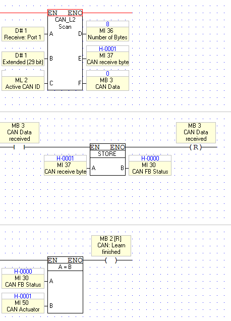
-
 Hi, I got V130 PLC, and I need to show some analog measurements on my display. When I try to type in russian, it just shows * no matter what I type. How can I solve this? Thankful in advance, Nikola Ljubinkovic
 -
 Hello everyone, I'm new to this forum, and to Unitronics products in general, so I'm sorry if my question is too basic. The question is about navigating through displays on a V130. I'll describe my problem with an example, since the application I'm working on is far more complex than what I need to show you. Let's suppose I have an application with three displays (namely Disp1, Disp2 and Disp3). There is a jump condition on Disp1 and Disp2 which jumps to the next display when I press F1 on the keyboard. I.e., if I'm showing Disp1 and press F1, then it jumps to Disp2; on the other hand, if I'm showing Disp2 and press F1, it jumps to Disp3. The thing is that when I'm showing Disp1 and press F1, it jumps directly to Disp3 (which I think it happens because when it loads Disp2, as F1 is pressed, it jumps again to Disp3). How can I prevent this? I've tried several approaches and none of those worked. I've tried both creating some logic in my app which triggers a Load Display block, and using the Jump Condition table on the Link&Jumps tab of the display editor. Some background about me... I'm new to Unitronics products, but I've worked with other PLC brands, and I have extensive background in programming and embedded electronics. Thank you very much. Juan.-
 -
Hi, I have Unitronics PLC V130-J-TR20 PLC, which is a master, and two Jazz JZ20-J-T40, which are slaves. I need two of the slave Jazz PLC's to communicate with master V130 PLC. I have made configuration in PLC Program for read and write, but it's not working properly. When i set bit for request to read PLC3 (MB100), it reads it normally. But, when i try to read PLC2, it reads same value that I have on PLC3, although Communication is OK with PLC2. I have read example project, and used it to configure communication between PLC's, like you can see in the images. Regardless of what I do, one of the PLC's is not working properly, communication says it's OK, but keeps reading values from other PLC. IP addresses are different, of course, and i have typed them correctly into the MODBUS IP Configuration, like in the image. On my Jazz PLC's I have done everything like Example project in U90 Ladder says. Is there a way of fixing this? Thankful Nikola Ljubinkovic
-
Hi, I have two Jazz JZ20-J-T40 PLC-s, and one V130-J-TR20 PLC. I am using zView SCADA. I tried to connect them via Ethernet by using switch, but I cannot use two different PLCs on this SCADA. Then i tried to connect them to SCADA via uniOPC, but communicating is just too slow. I have just one bit that goes from 0 to 1 in 0.5 seconds, and back to 0 in 0.5 (1 second pulse), just for testing, still it's too slow. It runs normally for like 2,5 seconds, and then just stops, and changes in 4-10 seconds, or just freezes for 2-3 minutes, and then changes. My PC Spec are not in the way of this, I am sure of that, i have tried it on my weakest and strongest laptop, still exactly the same results, too slow with just one bit for each of the PLCs, that is 3 bits total. Does anyone had the same problem, is there a way of fixing this? Regards Nikola Ljubinkovic
-
I am trying to use a pulse flow meter to measure the drain flow of a hydroponic garden system. We are wanting to use this to alarm if we have low flow in certain parts of the system. This is a low budget project so I am having to work with what I have. My V130 plc only has two high speed counter inputs and I would like to measure the pulse flow in four different areas of the system. So my question is, is there a way to read the low freq pulse of a regular digital input? The freq of this input would be no more that 20 pulses per second. I have been able to use a counter to count the pulses but I am not sure how to divide this number by a period of time. By the way I am new to programming. This is more or less a project for me to get some hands on practice. Thanks,
-
 Ok guys, first time attempting ladder programming here using a V130-J-R34. I am using AN0 to get signal from a 3-wire pressure sensor. Brown/Blue goes to +/- 24Vdc and the black wire is my signal. I get a 4-20 mA from the sensor and according to the default jumper settings of the V130 the AN0 is set to accept current as input. I am trying to perform a simple linearization to display how many bars my sensor reads. Since the memory of the analog input is 10-bit this is how I set it up: (see attachment) The logic is that being a 10-bit memory the max 20mA corresponds to DEC 1023 and min 4mA to DEC 204. Then this is converted to 0-10 bars. However it does not work. My MI0 reads always zero and the output MI1 is stuck at -25. Any ideas here about whats wrong? Cheers
-
 Hi, I`ve installed V130 with simple web server application, at remote facility. I ve succeed to connect remote web server from control centers PC and it looks like it is working fine but ocationally link breaks. Rebooting either remote router (HG531 v1 Firmware version HG531V1V100R001C90B017) or V130 recoveres the link. I ve set SB 168 already but problem persists. Is there any other way to automate lost link recovery process?
 -
I am trying to use an Interrupt HSC with a V130-33-B1 and a Ex-D16A3-TO16. when I try to upload the project to the PLC I get a message saying that Interrupt HSC is not compatible with my hardware configuration. I have looked all over documentation to find out if this is true or if i have something else configured incorrect, but have come up blank. Can anyone confirm that HSC on an expansion is not compatible with the interrupt? I know that immediate routines are not compatable with the V130-33-B1 but there is nothing about the interrupt.
-
I just bought a V130-33-B1 and a EX-D16A3-TO16 expansion module for a project. I need to set up a HSC Interrupt but the project tells me that the hardware configuration is not supported. there is not documentation anywhere that says HSC interrupts are not supported with the 33-B1 is this true? I know that Immediate elements are not supported on expansion modules. Can anyone confirm or offer a work around?
-
 Hi, Here with attached my program which is half way done for test rig. I couldn't enter the values or even go to keypad entry mode. Please anyone suggest me what i did wrong. Thanks in advance. 19_10_13_TA24.vlp
 -
 I am trying to input a String via HMI Keypad as MI -vector on V130 is there an example file ? thx
 -
 I am using a V130-T4-TR6 and need to verify some information on the HSO output that seems contradictory between the tech spec and the V9.5.0 help file. Per the tech spec, the HSO freq. range is 5Hz to 200kHz. According to the help file, a value of 0 can be used but is not mentioned in the tech spec. It seems that the 0 value is used for a constant "ON" signal. Is this value available in the V130 and if so, please verify its function.
 -
 Hello, I am trying to set up a V130 to send out text messages. I am using the Enfora modem and have set everything up correctly I believe. I am using COM1 and have changed the internal jumpers to RS232. I have the COM INIT 1 block running on power up with a baud rate of 9600. I have used the Modem Services to 'Prepare PLC-side modem' with a baud rate of 9600 as well. When I plug the modem into the v130 and cycle power the connection fails (ie SB81=1). Can anyone give me insight as to what I am doing wrong? Thank you, BenB
 -
Hello, I have recently posted asking about how to get the Enfora modem to connect to the v130. I was able to accomplish this by placing a number in the 'Number to dial' box in the modem settings screen. I just put in my cell phone number to test and the modem connected after that with a signal strength of 14. I do not know what the Number to dial should be set as though. I also am trying to send a text message and have everything set up to do so. Whenever I press the #1 button to activate the request to send the Modem Busy bit changes to 1 for a few seconds and then switches back to 0. None of the other status bits change when I do this however. I believe the request to send does change but is activating the SMS Send FB and is then clearing itself before I can see the change. Any help with this is greatly appreciated! BenB


