

hEllberg
-
Posts
8 -
Joined
-
Last visited
Content Type
Profiles
Forums
Gallery
Events
Blogs
Downloads
Articles
Media Demo
Posts posted by hEllberg
-
-
4 hours ago, Flex727 said:
Then you just need to select RESET as the Power-up parameter NONE is the default selection):

All of the PLC memory is retained through power cycle by default (if the battery is good). This includes the state of Outputs. This isn't an issue with Direct Coils, but if you use Set & Reset Coils, then you need to pay attention to this detail.
Your Reset Coil has the logic property of Reset, but when in online mode, the red is just indicating the state of the bit, on or off. Any type of coil will indicate the state in the same way. It is different when the bit is a contact. Contacts will show power flow and thus an inverted contact will be red when the bit is off.
Thank you!
-
18 hours ago, Flex727 said:
Just a few observations:
1) Do not place multiple logic networks in a single ladder rung.
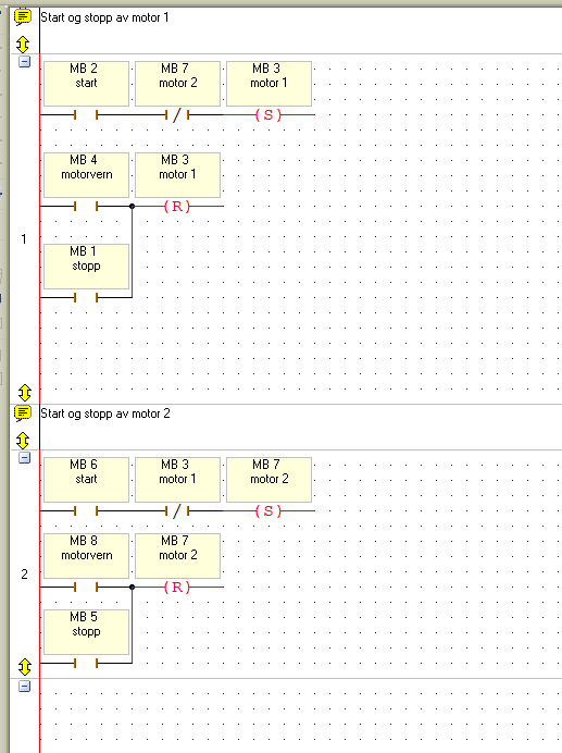
2) What did you use to start Motor 2 while Motor 1 was running? HMI pushbutton, or what? I agree that if MB 3 is on, then turning on MB 6 should not turn on MB 7.
3) You misunderstand what the red lines mean. If a bit is red, then that means it is on (or True). The type of coil is irrelevant to the fact that it is on.
1) I won't do that from now on 😎

2) I used a HMI pushbutton that I pressed on my VirtualPLC software. When I placed the networks in different rungs it seems like I can't run both motors at the same time anymore, so that problem got solved.
3) I understand that, I just explained a bit weird. I don't understand why my reset bits gets turned on when I start one of the motors. Anyways it doesn't seem like it has anything to say.
Now if I do an online test and I start motor 1 for example, then do some changes to the program, download it to the VirtualPLC and then go back to the online test. Motor 1 is still running, and I have to press the stop button to stop it. Is this because I'm using Memory Bits? I want the motors to be default in stop every time I restart the PLC.
-
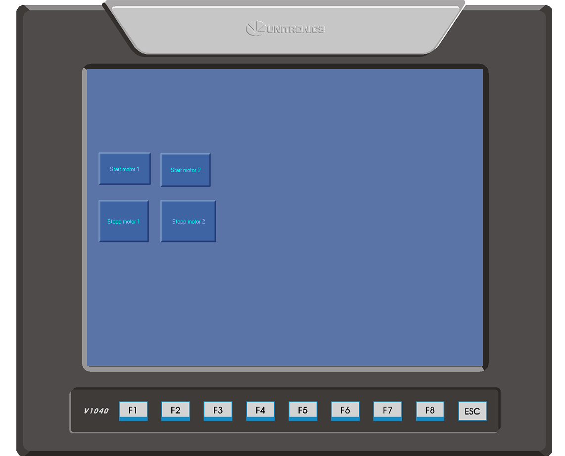
I tried making some really basic program with 2 motors. Motor 1 can't start if motor 2 is running and vice versa.
If I start both motors they both show red on the output. Meaning that they could both run at the same time, even tho I'm fairly certain I programmed it right. Is this just visual or would my motors actually start without interlock? Also the reset coils goes red when the set coils gets a signal.
-
Is it possible to use the SR flip flop and connect inputs in parallel on the reset input? Or do I have to use set and reset coils?
I tried but I could only connect one input on the reset input.
-
Hello again,
How could I make something like this in VisiLogic?

-
Hello,
I'm using the VisiLogic software. I'm familiar with Siemens plc programming, but the addressing in VisiLogic makes me confused. I bought myself VirtualPLC so I can train at home.
What I need help with:
When I programmed Siemens PLC's I was used to use the addressing: I0.0, I0.1 and Q0.0 and Q0.1 etc.. What is the equivalent of this addressing in VisiiLogic? I just want to make a really basic ladder program, and then work from there, but at this point I don't know where to start.Also with Siemens software I could make one net with a memory input, and then define how this memory input would be activated in another net. How can I do this in VisiLogic?
All answers appreciated, got my examination as an automation technician in some months and I will be using the VisiLogic software for my examination task, so it would be great to learn the software.


Need help with basics
in Vision & Samba PLC + HMI Controllers & VisiLogic Software
Posted
I only use VirtualPLC for myself private to get to know the VisiLogic software a bit, also it does seem to do it's job. The VirtualPLC program is really easy to use.
I do it just for learning and nothing I make will be used in production. At work I do have a PLC that I will program for a training station.