

DaveE
-
Posts
83 -
Joined
-
Last visited
Content Type
Profiles
Forums
Gallery
Events
Blogs
Downloads
Articles
Media Demo
Posts posted by DaveE
-
-
I always knew you cared Joe
")
Yes SI 103 and 104
I was only using socket 0 and 1
-
Just if anyone cares, I fount the issue
The socket was going to sleep after the time outs ended, and it took a while to wake them back up again
I set them to the maximum and it still wasnt enough, I ended up having to set the time outs to 0 and then I always got the data coming in.
Not the way I wanted to do it, but hey it worked
-
Hmm
seem also to remember some issue with the timing that I had, not sure exactly what now
but what fixed it was starting a timer from when the first byte was received before moving on

-
Just a thought, because its hard to tell, but how many characters are you sending
I had a similar issue when my buffer length was too short, therefore it was clipping the message off
-
Good Evening
I have recently downloaded this version
Is it just me or is it really twitchy?
I stops, goes non responsive so frequently its doing my head in
Running Windows 10 64Gb ram, I 7 processor, so it shouldnt be the computer. Never had an issue with 1.28 version
any thoughts?
-
Aus
Yes you are correct scans of the camera (slip of the brain)
The issue I have is that even if I just stay on the first 5 lines of the main routine, and dot run anything else at all, the MB33 and the MB38 do not increment to start with, and then "wake up"
(Those are attached to the TCP/IP scan)
One thing that was suggested to me today, which I forgot about was to go into info mode and scan then, to see if the PLC is getting something and doing nothing with the data, or not getting anything

-
Good Afternoon
I have a V570 that is connected over TCP/IP to 2 cognex cameras. for some reason that I cannot establish when I start the system, the first 3 or 4 scans will not trigger the scan. Neither MB33 or MB38 go high when the camera is triggered to take a picture. After the first couple of scans it seems to start working properly. The logic in my head tells me that the camera for some reason isnt sending the scans over properly, but that doesnt make sense to me either. This is the initialize in the main routine.

If I go to the sub routine (and yes it is being called) if the positive edge of MB33 or MB38 is not seen, the whole system stops.
I have to be missing something, I have time outs set, so If I lose communication for some reason is starts again. I am missing something and hoping a genius out there can assist my brain


Thanks
-
I had the same issue, however mine was my fault...
Timers were saved and loaded up on start up and then stored and recalled on start again, if they changed
Needless to say instead of loaded the saved number, I saved zero, and all my timers went away!
-
Thanks guys
I guess I will find out if Flex is a genius
-
Good Morning
I have a new project in which my customer wants the system to scan a barcode, connected either via serial or ethernet and then record the barcodes scanned.
That bit is no issue, was going to use a data table and store all of the scans done, and use the last entry to give him a total.
However he has just thrown a wrench in what I had planned as he wants the details on the screen too.
Not only that he wants to show a totalized list of the barcodes scan with a subtotal for each barcode scanned during the day, and I am not sure how to created that on the PLC. And I will not know what those barcodes will be, could be one barcode, could be 10 different (they have 3000 different products, but fortunately not all running at once.)
I will be using a V570 for this.
Has anyone got any knowledge of doing this type of thing previously, or even if its possible?
Thanks
-
Good Morning
I did this (and do this) using a data table and a sensor at both ends
After the camera is triggered, store a bit in row 0 of a data table to "say" either " good read-0" or "bad read-1" and then increment the row in the data table, so the next trigger comes into the next row.
Then at the reject end I read row 0 and if that bit is true I set the reject, if false I unset the reject (just to be safe)
at the end of all that I delete row 0 and decrement the row
works like a charm and no encoder needed.
also, major benefit is that you change product sizes, it doesnt matter, as you are counting products. Also you can put the reject where you like, who cares, its only numbers.
(Hint, if you go this way, make sure that you use plenty of rows when you set up the data table, when I started, I set the table for 30 rows, and needed 40 products before the reject eye.. oops)
-
well I found a workaround!
Had to extract the exe file with winrar, then go into the extracted folder and then double click the welcome.exe file
all smoothly from there!
All that work to start PLC coding
-
Sorry about image size, wouldnt let me upload anything larger
here is a link
https://www.dropbox.com/s/cascwlo9zjgt3z2/oops.jpg?dl=0
It is while trying to install
It reads the package content then fails
-
Good Morning
Just tried downloading and get an error message
Not enough room on C drive
I do however have 0.5 gb available
I ran as admin, and turned of my antivirus. Trying to install on Windows 7 64 bit professional.
Any thoughts??

-
Joe
Thanks for that, unfortunately it didnt work
-
Ok. Tried that
in the strings library it shows Hebrew ( I think)
however on the screen it shows differently. Looks like O’s with accents and umlauts
-
Good Morning
I have a customer who wants to change between Hebrew and English
I know how to actually change between language, done it many times with English/Spanish
Its how do I get Hebrew to show up in the Strings Library?
Thanks in advance
-
Sorry for the delay
You are correct Joe, its not a good idea because it didnt work
I had to set one on power up and then unset that and reset the one I wanted at the correct time!
Makes sense now I think about it, but who thinks??

-
Sorry. Typo. Put it down to old age
V200-18-ET2 was what I had issues with
-
Just for everyones info
turned out that the ethernet cards V200-18-E5B were bad, all three of them, despite them being brand new
Got new cards in worked without a flaw
-
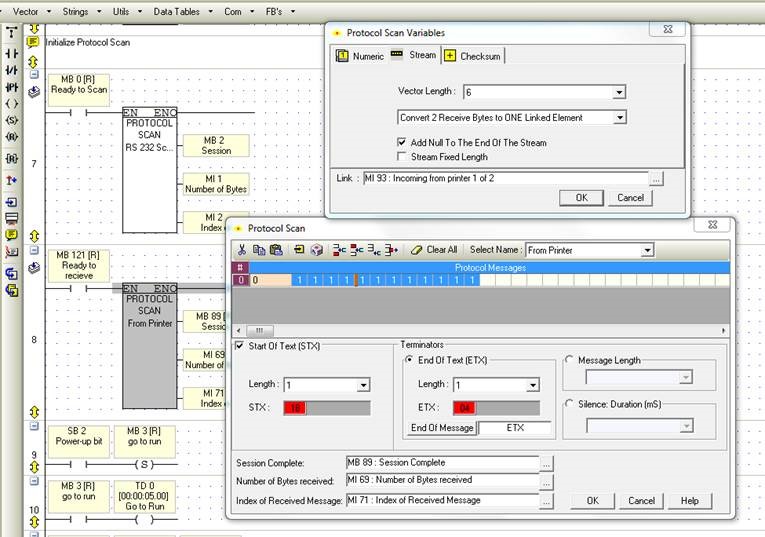
Good Morning
I have a program, in which I need to receive using RS232 from 2 different units (One is a hand held scanner, and one is an Inkjet printer)
I have configured both protocols correctly and I see in info mode that the PLC is receiving them, but the strings they are receiving are not being sent to the correct place (I don’t see where they go)
In the main program I set this

My thought was that when I set MB0 the plc would get the code from the barcode scanner and when I set MB121 the “from printer” code would be received

As you can see that when I get the correct result I would then go to the assembly code scan
I also set the Barcode scanner protocol and reset the printer protocol
However when I run the program, it doesn’t “see the scans”, however when I am in info mode I see them
Thoughts please, what am I doing wrong
Thanks In advance
-
Hi Cam
Turns out that even the basic program, just initializing the card and then opening the sockets, the PLC isnt doing anything
However when I run the same program in a Samba it works
weird
PLC is at Unitronics now being dissected I guess,, I have 2 doing the same thing!
-
Hi Cam
SB150 does nothing at all, just sits there looking at me.
SB151 and SB153 are both on, so I know I have an ethernet connection
and on 2) that is my intention at the moment, will be changed if I can ever connect!
-
Good afternoon
I am trying to send files through ethernet from the SD card. I have downloaded the FTP client example, and have modified it a little bit so it may work in my application.
I will soon be modifying it again, so that it automatically connects, but at the moment I am happy to do things manually (well I would but I cant get it working.)
What should be happening, is that I scan a barcode, which then creates a CSV file on the SD card (that bit is working!)
Then what happens it takes me off to the FTP page. When I press the connect button, it is meant to connect me, but I get nada, nothing!
Can someone tell me where I am going wrong? Thanks guys
Code is attached to this message. The main routine initializes the card etc then I go to the FTP subroutine to do the rest


V570 TCP-IP Scans not getting some data
in Vision & Samba PLC + HMI Controllers & VisiLogic Software
Posted
Aus
Talk about desperate!!🤪