

SvjatoslavsKrasnikovs
-
Posts
13 -
Joined
-
Last visited
Content Type
Profiles
Forums
Gallery
Events
Blogs
Downloads
Articles
Media Demo
Posts posted by SvjatoslavsKrasnikovs
-
-
Hi. Finally found a 2W 180 ohm resistor. Connected everything according to the schematic above, and well, nothing happens. The 2W resistor is also overheating over the time.
-
Heh, seemed that my potentiometer is simply not powerful enough (burned it). I'll find a "larger" resistor, then retry. I'll post full experiment report when I'm done.
-
Thank You so much for trying to help me. I've sketched a rough connection schematic, according to what You've suggested. Is it right ?
On the JZ20-PRG to JZ10-22-CS10 side, the connection is standard (through MJ20-CB200 cable). However, after the DB9 of MJ10-22-CS10 I'm braking the connector (DB9) into individual cables (on a breadboard). The +24V will be used from the PSU (I'll use bench PSU , with GND connected).

-
Does V130-B1 need an rs485 extension module ?
-
Any change to get a response ?
-
Thank You for the reply.
In the case of Samba 35 - what's the least expensive RD485 add-on module I'd need ?
In the case of M91 - do I need any RS485 add-on modules for those ?
-
Hi, I'm running an Arduino-based home automation system. My custom-made Arduino clones are communicating over a RS485 network (configured as 8N1) using Modbus RTU protocol. Thing is that I want to have a reliable, industrial-grade PLC in the network, in order to monitor my Arduino-based sub modules. Basically I need a cost efficient Unitronics PLC capable of connecting to RS485 network, The ladder program is expected to be non memory hungry, also I'm fine with good old 2 line display. The PLC must be able to connect to the RS485 network without the use of any extension modules/communication modules /.etc (native COM port on a screw terminal).
Any suggestions?
Thank You.
-
Thank You for the reply. Well, I do not have an access to MJ20-RS module at the moment. All I have is MJ20-PRG, MJ20-CB200 and MJ10-22-CS10.
If I'll power up pins 1 and 6 of a MJ20-PRG through MJ10-22-CS10 (just like in a picture attached) will I be able to use my MJ20-PRG as a RS232 module ? Or do I need to change the schematic in any way (attach series resistor to +5V line, etc.) ?
Thank You
.thumb.jpg.8e150560664c56e1d88a5c17357dca4a.jpg)
-
Hi. I have a Unitronics JZ20-R16 (Jazz2) controller I’ve programmed to run a simple air ventilation system in my house (The thing is running great btw.). I also have a self made Arduino based data logger (I use it to monitor and log my energy consumption, temperature, etc.) I’m not building those things or mass producing, Arduino electronics is my hobby - I just use it to stay sharp.
So I decided to cross-integrate my air vent. Controller with my data logging unit (I want to see the status of my air vent. Controller unit on Arduino). So for starters the task is to simply send a 16bit int to Arduino and receive another 16bit int from the Arduino.
The communication protocol of the choice was MODBUS through RS232 interface (as I already have MJ20-PRG; MJ20-CB200 and a MJ10-22-CS10). I’ve decided to use JZ20-R16 as a Master (Arduino as a Slave) in a 9600 baud 8N1 configuration (default for JZ20-R16). For Arduino’s RS232 interface I’ve used TTL-RS232 converter (MAX3232 based) :
Experiment 1:
In order to see if the Arduino’s MODBUS feature is working I’ve connected Arduino to my PC using the given connector and a RS232-USB converter. Arduino was configured as a slave and ModbusPoll software (http://www.modbustools.com/modbus_poll.html) simulated a master. I was able to both read a holding register from Arduino (03) and also write a register (06). Those are the desired options.
Experiment 2:
In order to see how MODBUS is working on JZ20-R16 I’ve hooked it up to my PC using my MJ20-PRG; MJ20-CB200 and a MJ10-22-CS10 later connected to RS232-USB converter. I’ve uploaded a program (by pressing buttons 1 and 4 I send an int or correspondingly request an int from slave):
(see in uploaded files)
It make the JZ20-R16 work as a Modbus master on a RS232 interface. In order to simulate a slave I’ve used ModbusSlave software (http://www.modbustools.com/modbus_slave.html) . Once again, the combination worked perfectly. Once again all the required commands worked.
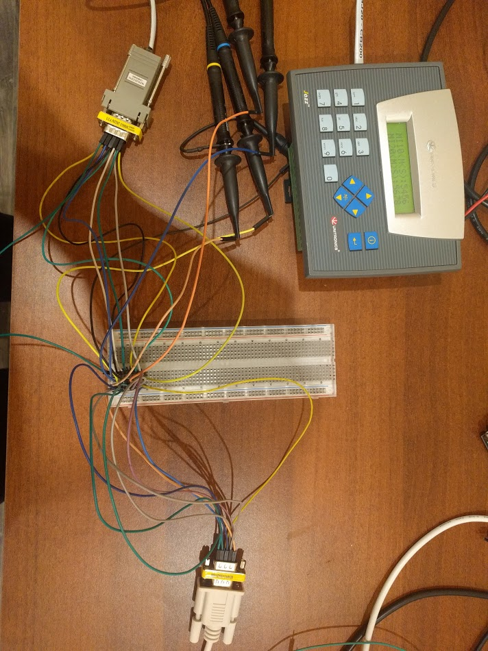
Here’s the photo of my hookup:
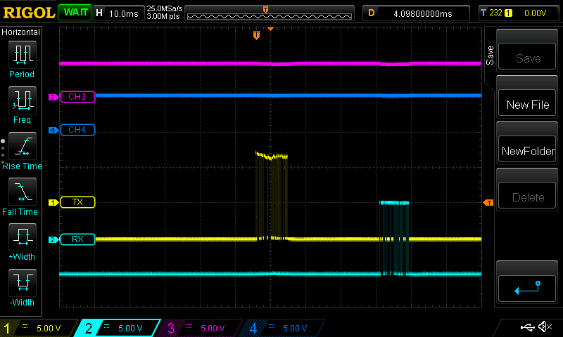
Then I’ve noticed a possible cause for future problems : lines 4 and 7 of my MJ10-22-CS10 are actually used in this communication. It turned out that the RS232 communication with JZ20-R16 require 6 wire communication instead of 3 wire communication I’ve expected from RS232 interface. Due to the requirement of RTS and DTR signals!
I’ve turned on my scope and actually saw those signals on pins 4 and 7 of MJ10-22-CS10 connector going high after the “handshaking” with my slave simulator was done.
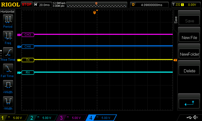
With PC USB disconnected:
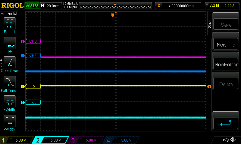
PC USB Connected:
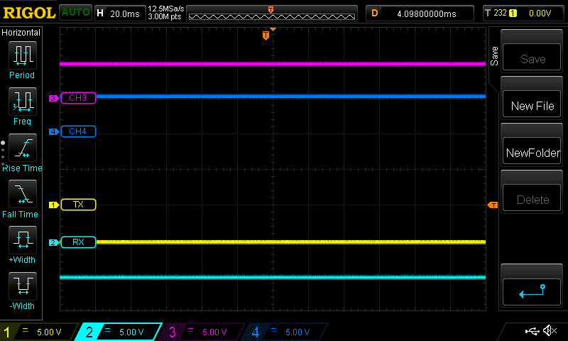
MudbusSlave after “handshaking”:
Successful communication:
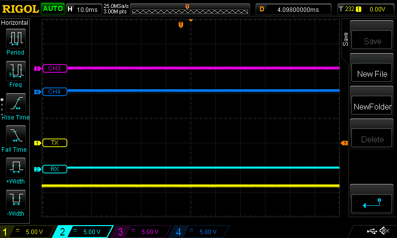
CH3/4 are the DTR and DTS signals correspondingly. At this point I’ve realizes that sue to those signals I would not be able to connect my Unitronics to my Arduino, as the TTL-RS232 connector simply do not support DTR and DTS signals. So after hooking up my Arduino to Unitronics I see the following on the scope:
Both DTR and DTS signals are on 0 instead of HIGH, which prevents the JZ20-R16 from accessing the modbus.
The questions:
-
Is there any chance to make JZ20-R16 communicate over RS232 without use of DTR/DTS signals?
-
Is there an option to tweak those signals (connecting them to +5V permanently)
-
Use of other TTL-RS232 converter?
-
Any other way to make Arduino and JZ20-R16 communicate over RS232 interface using MODBUS
Thank you for the patience.
-
-
Hi,
I am facing troubles while trying to log and later display time using Jazz2 controller. So, I'm trying to make an error log. When the error occurs I store current content of SI31 (RTC time) to MI (MI33 in this case - so far it's working). Then in order to display the error I pass MI33 content to MI41 (MI41 is linked to Time Function variable (in CT format) that is then displayed on HMI) . You can see the whole process in images below. The problem is that in the end, the content of MI41 (decimal 1500 - which I corresponds to 15:00 time) is then displayed as 05:DC on the HMI display. I guess the problem is caused due to DEC/HEX conversion. Any idea how to fix this ? Thank You.


-
Thank You for help.
-
Hi, I'm learning ladder by the aid of Unitronics JZ10-11-R10 PLC. While writing my 1st program I've ran into issue. The thing is that I can not find a way to input MB value from HMI. Are there any ways to do it ?
Thank You

.jpg.c10cef38f7d602e483962dc2ac410853.jpg)


Modbus connection to Arduino through RS232 interface problems
in Jazz, M91 PLCs and U90Ladder
Posted
I'll try to reproduce the experiment ASAP. I do not have the MJ10-22-CS25 though. I have a MJ10-22-CS10 can I use it in the same way ? Thank You.