

C_R_PLC
-
Posts
45 -
Joined
-
Last visited
Content Type
Profiles
Forums
Gallery
Events
Blogs
Downloads
Articles
Media Demo
Posts posted by C_R_PLC
-
-
On 12/5/2019 at 12:24 AM, Ausman said:
And in re-reading your post, I'm assuming that the adapter is USB at the laptop side with an ethernet out? This seems different to what you say here:
Sorry, originally I only used USB -> Micro USB for any PLC connections, I got the USB (PC) -> Ethernet purely as an alternative when I couldn't get the USB -> Micro USB method to work in hopes that it was just something with that port on the PLC.
QuoteDoes your ethernet adapter communicate to networks/WAN/www normally if you use it that way instead of wireless? Any error here might point you in the right direction. Perhaps the adapter needs to work with a crossover cable.
I haven't tested the adapter on my PC for internet connectivity, will test that today.
https://www.amazon.com/Cable-Matters-Ethernet-Adapter-Supporting/dp/B00BBD7NFU/ref=sr_1_4?keywords=usb+to+ethernet&qid=1575641655&sr=8-4
This is the adapter that I'm using currently. The USB -> Micro USB cable is just the one that comes with most of the Unilogic/Visilogic PLCs. -
Not sure what's causing this but I'm just about out of ideas. On my previous laptop I was able to connect to the PLC via USB after a bit of trial and error, but while testing a program the motherboard on that computer fried and on this new one I've had absolutely no luck so I'm stuck uploading with a flash drive which is not ideal. The PLC itself seems to work perfectly other than this connection issue but I am worried that something about whatever happened to that laptop damaged something the PLC, but it seems unlikely.
So far I've tried:
1. Fully turning off the firewall.
2. Allowing the Unitronics Unilogic and Unitronics.Notifier through the firewall.
3. Connecting the USB/ethernet cable at all stages of start-up.
For the ethernet cable connection I'm using a USB -> Ethernet adapter, which may influence it in some way but my laptop doesn't have a built-in ethernet port. Running Windows 10, Unilogic is fully updated, and the firmware on the PLC is fully updated. -
On 6/23/2019 at 3:22 PM, Joe Tauser said:
Specifically, what UI object types are you frustrated with?
It's mainly just the overall amount of empty space on the Unilogic version, I'm referring more to the functional UI than anything that goes onto the HMI.
For a point of comparison below is my screen on the Unilogic progam vs the Visilogic program. Note how many more rungs I can see, how much more information is easily reached without scrolling, etc...

Everything is just much more spread out and there's so much blank space that isn't showing anything useful on the Unilogic UI. -
I've recently been teaching myself Unilogic after using Visilogic for about a year and the thing that sticks out to me the most is that while Unilogic definitely looks more "modern" the UI is absolutely horrible and wastes so much space. To the point where I'm having issues using the program on a single screen compared to Visilogic's much more condensed and less cluttered style. Is there a theme or setting that I'm missing that could lower the entire UI scale or something along those lines?
-
 1
1
-
-
Okay tested it after STOPPED and after a RESET and still no luck. The last thing I can't find is how to full reset it to factory, is that in the same menu set?
-
Okay so I have double checked both the cable and the program itself and I don't believe those are the issues.
In INFO mode the COMM port details are:
COM1 - RS232
Prtcl: PCOM
lgn Brk: N
Settings: 9600 ,8,n,1,N
Tx/Rx: 00000 00000
Silence: 8.75ms
In INFO mode I am not seeing a way to reset the PLC or STOP the PLC, is there something I'm missing with that? I don't actually have an SD card unfortunately to use that function so if that's the only way to do it I'll have to go out and get one. -
17 hours ago, Ausman said:
Have you tried other cables? (the first thing to try.....you wouldn't believe the coincidences and subsequent frustrations that happen with a cable failure!!)
Did your program change anything relating to the com port?
What is the com port showing in info mode?
Can you access it at all in boot mode?
Have you tried doing a full reset of the plc using info mode and then loaded your original progam back in after doing everything else needed?
cheers, Aus
So I have not tried a second cable, although I did double check this cable on another PLC which worked as expected. So I can definitely try a new one.
The program does not affect it to my knowledge.
I have to test these next 3 things, will report back with my results soon.
14 hours ago, Flex727 said:Uh oh, is this a problem with Windows updating something? Try to re-install the driver for your USB to serial driver.
Tried reinstalling the drivers, checking for updates, all that good stuff. The wire still works on the other PLC I have here so it doesn't seem like it's a PC issue.
5 hours ago, stembera said:In case of problems with serial ports, it is often useful to try to download program when PLC is STOPPED (you can do it from INFO mode).
If you are in troubles with COM port init, try to load "Last known good" version of your software from SD card. It helped me sometimes.Will test this and report back, thank you to everyone for the tips. Hopefully one of these is the culprit.
-
After downloading my program onto the PLC I'm working with I had to revise it a few weeks later and went back to download the new version, but now it's giving me a comms error no matter what I try and do to fix it. I've tried every baud rate, multiple ports on my PC, checked jumpers (which from what I can see are correct but always seem to be a point of error for me), and tried a blank program as opposed to the one I want to download.
Connection is PC USB -> MJ 10-22-CA25 adapter, all hardware is the same as the initial upload. -
On 8/19/2018 at 12:35 AM, Cara Bereck Levy said:
I love this thread--very good example of what the forum is all about
")
Chris, if you haven't come across it, you may want to check out the Help topic Program Sequencing.Also, right-clicking the left-hand rail will open a menu that offers a view option called 'power flow'. This shows little arrows in the direction of flow--which is a handy thing as well.
Thank you very much, definitely very handy tools. I was in the process of trying to wrap my head around the links/jumps sections.
This has very much been a good example of the more I learn the more I know I don't know lol -
10 hours ago, alagbawale said:
Thanks Joe T you are very right, I have the idea but I don't know where and how to start and I go through the examples on the software but not getting the starting point. Please what can be done to this to help my zeal and level?
So I can only say from my personal experience but I found that going on YouTube and basically watching a ton of videos helped me the most. I started with the bare basics on relays and worked my way from there.
My first bunch of videos were from here... https://www.youtube.com/user/plcprofessor/videos
His earliest videos go very much into detail on the basics of relays and then goes up to programming in RSLogix500, which is obviously not Visilogic but the ideas carry over pretty well. You'll want to start with his Basics01-14 series, and then watch his PLC Lecture series from 01-12. Also take lots of notes because he moves at a pretty rapid pace and you'll definitely want to be looking back every now and then.
After that you should probably head to the Visilogic YouTube page to get the specifics on how everything you just learned applies to Visilogic, namely their playlist on Visilogic Logic and Application. Found here... https://www.youtube.com/user/UnitronicsWebinars/playlists
There are playlists for other more specific things that will definitely help you so I would say go to those for more specific questions. Your biggest tool past the basics however is the help/examples page in your actual Visilogic program, that will go very into detail about how things work and has answers for pretty much any question you can think of that isn't hardware based as long as you take the time to learn it.
Past that it's just a ton of trial and error, and learning from every mistake you make. It helps a lot if you have a goal you're trying to accomplish which it sounds like you do but this step of the process took me a few months of like 6-8 hours a day of studying, so be prepared to put some work in. It may not take that long for a sloppy, bare-minimum type approach but I would say that should not be your goal.
Hope this helps,
-Chris -
I understand, thanks for taking the time to explain it. That whole notion of the compiler not necessarily doing what you expect it to never even crossed my mind. I just had the basic understanding that it read left to right and up to down, but even that's not really the compiler aspect of it.
-
Ahh okay I see, I'll try and avoid doing that until I understand more how it affects the compilation process. But that logic is also much more straightforward than the storing that I was doing in mine so I could see why that is able to be combined as opposed to mine.
In that example what is the purpose of SB 1? Wouldn't just a line from the left rail be enough to always have that powered? -
6 minutes ago, Flex727 said:
Yes, that would count as multiple logic threads in a single ladder rung. It will often work but it is extremely poor programming practice. Remember that what the PLC executes is compiled code, not ladder logic. The compiler may not compile code like that exactly in the way you expect. You can be certain what to expect when the logic is in separate rungs.
Ahh okay that's exactly what I meant by behind the curtain, I had no idea about the differences between compiled code and ladder logic. Will definitely fix those wherever I see them. I always feel weird asking for explanatory questions like that because I know it can come off as like disregarding the advice, definitely not how I meant it.
-
On 8/6/2018 at 5:14 PM, Flex727 said:
The most glaring thing to me is placing multiple logic threads in a a single ladder rung (Password Entry routine rungs 1, 2, & 5). DO NOT DO THAT! It may work, but it is extremely poor practice and will often not perform as expected. You will not run out of ladder rungs, so break all logic into simple components, one per rung.
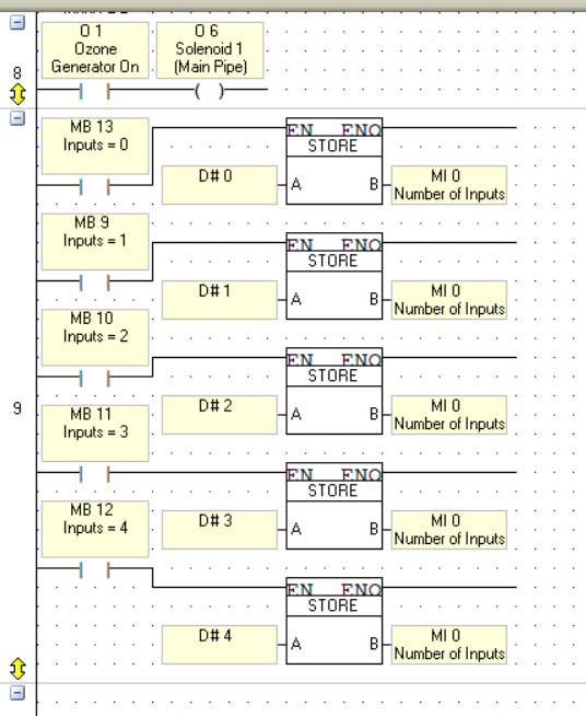
Just as a follow up question would the attached picture count as placing multiple logic threads in a single ladder rung? And if it is what is the harm in something like this? I only ask because to me it looks neat this way but if there is a more behind the curtain reason not to do it then obviously that overrides looking nice lol
-
On 8/6/2018 at 5:14 PM, Flex727 said:
The most glaring thing to me is placing multiple logic threads in a a single ladder rung (Password Entry routine rungs 1, 2, & 5). DO NOT DO THAT! It may work, but it is extremely poor practice and will often not perform as expected. You will not run out of ladder rungs, so break all logic into simple components, one per rung.
One other thing is ALWAYS use a positive transition contact for HMI calls. Although the one time you used a direct contact, it appears to me that it will only be on for a single PLC cycle, so it's okay in this case.
I didn't dive into the logic itself, but nothing jumped out at me when I reviewed it.
In general, when I write a program I only have two things in the Main Routine - Power-Ups then subroutine calls. Everything else is handled in subroutines.
I'll try to take a look in more detail later.
Thank you so much for responding, sorry my own response was so slow. The job site I'm working at doesn't have very good internet and it just totally slipped my mind. Definitely will fix the multiple logic threads and the Main Routine parts, this program is the culmination of a few months of a lot of trial and error so the fresh eyes definitely helps.
On 8/6/2018 at 5:18 PM, Flex727 said:By the way, I should have also mentioned that, for a self-taught newbie, your program was far better than I'm used to seeing from beginners - certainly better than the first stuff I did (which makes me cringe when I look back at it
).
Hah well thank you very much, I can't imagine you'd look so fondly at my first few months of struggle but it's good to know that some of the things I noticed and learned from proved to be going in the right direction.
On 8/7/2018 at 11:48 PM, Joe Tauser said:A bold move, Chris. "Here's my code - tell me everything I'm doing wrong". Truly a sign of humility, which is rare these days.
In addition to what Flex says-
Don't rename "Main". It's now confusing as to which subroutine is the caller for all the others.
I didn't see any network comments. I know it takes time, but it's good practice to describe what you are doing as you do it. When you go back and look at the program a year from now you'll be wondering what in the world you were thinking.
You've made good use of subroutines to separate functionality. A+.
Try to avoid vertical lines connecting coils to function blocks. The Lizard Brain wants to see a continuous straight line for a logical statement.
I personally like to put all the outputs in one subroutine (in order) and call them with MBs from other subroutines. Makes troubleshooting easier.
I also like to make a subroutine called "Display Control". Put all your display calls and any logic that is display oriented (like the password stuff) in there. Once again, easier troubleshooting.
I didn't see you make any use of the "Links and Jumps" tab on any of the displays. Considering you're calling the same display from three different displays, you may have done this on purpose. But also consider the power of Unitronics to move some of the logic out of the ladder and into the displays. This will reduce ladder code clutter for non-logical things like basic display calls.
This is not horrible code. Your rungs are relatively small and concise, which is good.
As I said with Flex thank you very much for the response. Sorry for being late on my own side.
The renaming Main thing and network comments definitely makes sense to me, I think that may have stemmed from me knowing I'd be the only one to ever look at it but it makes total sense that it's just as much there for me as anyone else reading it. I've definitely had times where even after a week or so of having to do other things I came back and had to basically relearn what I'd written. I hadn't even considered the Output idea, I think up till now where I'm a little bit more comfortable with everything I really needed to see the whole logic string together but moving forward I will definitely transition towards a more usable/troubleshooting friendly approach. Would you say the Display Control subroutine is similar to what I did with the Password Entry subroutine? Or should mine be split up more?
Could you elaborate on the vertical line statement? You're referring to Rung 6 vs Rung 8 in the attached picture? I think mainly I'm just making sure I'm understanding what you mean by function block.
As for the Links and Jumps I knew they existed but hadn't delved into using them at all, I'll definitely look into how to use those because I do like the idea of getting rid of some of that clutter. Things like that are kind of what prompted me to ask this because some parts of the code just seemed extra cluttered compared to others especially around like looping timer setups and things of that nature. The Set Reset method I used was discovered kind of by accident but I'll link an older program I made that was basically the PLC version of a laundry machine cycle that really gave me a headache trying to figure out. It's all in Subroutine 4 and honestly I'm not even sure if it works because I haven't gotten to test it yet, but it shows off the timer issue I was concerned about in the initial post really well I think.
Thank you very much for the kind words, I think "this is not horrible code" is just about as good as I could ask for in all honesty so I'm happy to hear that.
-
For a little backstory I work for a small business that basically hired me to be their official tinkerer, they need it learned I learn it. So in my endeavors I had to learn PLC programming to make the program for a water recycling system for a laundromat. This was mostly done through YouTube and trial and error, which has led to me making programs that work for my purposes but I'm curious if I've developed any weird tendencies or bad habits in my little educational bubble.
The project I'm adding here is part of the program and I think shows most of the things that I'm concerned I came up with "unique" solutions to, namely my use of set/reset and timers. If anyone could take a look and see what they think I am open to any and all critique.
Thank you very much for your time,
-Chris
Don't mind some of my labeling, I wasn't sure what the technical name was so I used some very literal descriptions. -
As always Joe you are a savior for my mental stresses, that worked. I was copying the wiring I had for another sensor but a wire must be switched somewhere along the way that threw me off.
Thank you! -
This is the reading that I get no matter what I do.

-
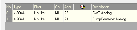
So after a lot of troubleshooting I'm officially out of ideas, so hopefully someone can see what I'm missing. My current set up is 2 4-20mA pressure sensors hooked up to the 2 analog inputs on the V350-35-r34. Wiring is + to PLC input, - to power supply 0v which is commoned with the PLC, ground to ground. The jumper setup is A A B B B from 1-5, so just the analog jumpers changed over.
I have tested literally every aspect of this setup, both sensors are a complete loop when tested, the PLC reads correctly if I use a 4-20mA loop simulator, all the wires are intact, I've tested it at the minimum distance of the wires, I've used 2 different PLCs, I've quadruple checked the program and all of that setup. I have literally no idea what is wrong at this point. Is there anything else anyone can think of to test or troubleshoot with this? -
Could it have something to do with the setup that I'm using to power it? I have a variable voltage output powering the sensor itself because it has to be set to 5V, so the positive and negatives are coming from that machine instead of the PLC.
-
9 hours ago, Ausman said:
And visiting this again, I think I see where your fundamental thinking is astray. I have a feeling that you are expecting to see MI0 showing the actual voltage. It doesn't work that way, it works the way Flex has pointed out in that analogue inputs generate numbers b/n a range, dependent on speed of read and type of input.
And I still want you to use a voltmeter!
cheers,
Aus
Okay, sorry for the late response. New day new voltmeter approach.
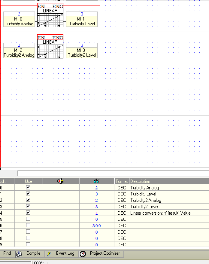
So with a voltmeter I get .756 volts when the sensor is clear and .950 volts when the sensor is covered. -
Ignore the second one, that was just me testing if it was the analog input itself, it's exactly the same.


-
1 hour ago, Flex727 said:
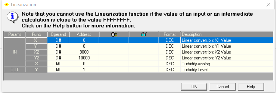
According to your link, the sensor output is only 0-4.5 volts. However, you should be able to make that work. The standard analog input on hte V350-35-RA22 has 14-bit resolution, which even at half scale will still give you at least 2 or 3 decimal places of precision. How are you measuring the 2-3 volts you say you are getting? Is this a direct measurement with a voltmeter, or are you linearizing the analog input on the PLC?
Direct reading through the MI that the analog input is going to. No matter what I do it only gives whole value readings of 1-4.
41 minutes ago, PA_DB said:If you have access to a 0-10V source you can inject a signal and see if it is a code/config issue or the device. Ramping up and down the scale will give you a change in your PLC value. In the absence of a source you can even use batteries 1.5/3V/6V/9V
Some likely things to check:
- Dip switch settings are correct as per install manual for 0-10V
- Hardware config settings are right
- Any scaling in your code is correct for the bit resolution of your model
- 0V connections as per manual
The help files and examples are always worth looking at
I've checked all that a few times now, I'm just trying to test this sensor so there isn't much actual logic involved. Jumpers are all correct and all that.
-
Title basically says the whole issue. I'm trying to get a usable reading from the sensor listed below, but it just seems to fluctuate between 2 and 3 volts even if nothing is plugged in. So my question is two-fold. Can I get a signal that is more precise than a whole number, and will that sensor even work with a PLC and if not is there anything I can get to interface the two?
Sensor - https://www.dfrobot.com/wiki/index.php/Turbidity_sensor_SKU:_SEN0189
Thank you very much for your time/help.


Can't connect PC to US5-B10-RA28 via USB or Ethernet Cable.
in UniStream: Hardware
Posted
So as an update I tested the standard PC -> PLC USB connection on a new US5-B10-RA28 that we're using at an installation and everything connected instantly as expected, so it definitely seems to be something with the PLC itself. May need to just warranty it and accept that it's not something I can fix at this point.