

Kikis
-
Posts
145 -
Joined
-
Last visited
-
Days Won
15
Content Type
Profiles
Forums
Gallery
Events
Blogs
Downloads
Articles
Media Demo
Posts posted by Kikis
-
-
Hello Edvin,
I asked the same question a few years ago in the forum and got great feedback, so have a look on the following topic:
http://forum.unitronics.com/topic/1584-analog-out-with-up-down-ramp/?hl=ramp
My application was to drive a pressure proportional valve for hydraulic control system via analog output.
For your application, I think that all VFD's have this feature as standard, did you check that your VFD is not capable of doing this automatically?
For example on Lenze drives, which is the VFD brand i use in my projects, you can set the total acc/dec time from the local keypad of the drive.
So i'm just sending the analog voltage command from the PLC and the drive automatically performs the ramping of frequency.
-
Hello Faze,
I created an example for you based on your description.
You can download the visilogic file from the dropbox link below:
https://www.dropbox.com/s/s1swbyl5ndx8vi2/PROGRAM%20EXAMPLE.vlp?dl=0
Hope this helps...
-
-
Hi Guys,
I was thinking that it will be very useful to have min and max value limit entries option for the timer Preset entry for Vision series.
In the following star-delta motor starting example, i use T1 as a delay in order to make sure that star contactor will be de-energised before delta contactor is energized.
Even though i use electrical interlock circuitry to prevent short-circuit, i always prefer to provide also an electronic safety.
Since response time of the PLC outputs is much faster than the response time of the contactor coils, T1 delay is required.
Today i had a call from one of my customers saying that there is something wrong with the motor of his air pressure booster which is controlled by a V130. The problem was that someone changed T1 preset value from 00:10 to 10:00 by mistake (10sec instead of 100mS).
Just a practical example of a problem in the real world!

-
Hello,
The following example shows how to detect change in MI value.
When MI5 value changes, MB8 will be on for one scan.

-
 1
1
-
-
Another needed feature is to have +10V power supply on the analog I/O module.
This is to be used as reference voltage for linear position transducers.
10VDC power supplies are hard to find.
So either i'am building it my self or if i have a free analog output i program it to continuously output 10V and use it as the reference for the pots.
-
In my applications (retrofits of injection molding machines) i need high resolution only for analog inputs. 12-bit analog output resolution is ok.
However i also need much faster response time for both analog input and output than the existing modules.
-
Hi guys,
It would be great if we had a high speed analog I/O combined module with 16-bit resolution for Unistream.
Conversion time should be 0.5mS or even less, if it's possible.
There are applications where is crucial to have such an expansion module.
-
Adding a relay would do the job.
Disconnect your input device from the PLC and connect it to a 24VDC relay coil.
If you are using PNP PLC input ,connect +24V of your PLC power supply to the common pin (Movable contact) of the relay.
If you are using NPN PLC input, connect 0V of your PLC power supply to the common pin (Movable contact) of the relay
Last step is to connect the normally open contact pin of the relay to your PLC input.
If the input will be triggered very frequently, it's better to use a DC load switching solid state relay to avoid electro-mechanical relay failures.
-
Adding EX-RC1 would significantly increase the total cost of the control unit.
I think i'ts better idea to use a third-party modbus I/O module.
-
Hi Johnny,
Regarding your question about stepper motors and 500Hz pwm...
Stepper motors are controlled via step & direction pulse.
You send pulses with 50% duty cycle to the driver and if the the direction signal is low motor rotates cw, while if the direction signal is high motor rotates ccw.
.
The speed of motor's rotation depends on the frequency of the output pulse and the resolution (pulse/revolution) of the stepper drive.
Most of the drivers are set by default to 400 pulses/rev (0.9 deg per pulse), but most of them have also the feature of micro-stepping.
The driver shown below can be adjusted by dip switches so that the resolution could be up to 50000 pulses/rev for more accuracy.
In order to calculate the pulse frequency needed, you need to know the desired rotation speed of the motor and the resolution of the drive.

-
Hello,
I'm attaching an example of how to load the current value of a timer in count up form into MI.
This is a 1 minute timer example, you can use 13sec timer and replace 6000 with 1300.
Then just use comparison functions to achieve the image sequence you need by storing values in another MI linked to images list based on timer's current value.

-
 1
1
-
-
You can use Modbus to communicate with a third-party HMI which supports this communication protocol.
-
Generally i think it's better to assign a unique bit in every subroutine and then "OR" them in another subroutine which runs unconditionally.
This way the code is much "cleaner" and it's more easy to troubleshoot.
-
1
-
-
I use Samkoon HMI's when extra HMI is needed for an application.
Communication is achieved via Modbus using the Unitronics Programming cable (No extra cable needed).
This is a cheap Chinese brand but i use them for 3 years now without any problem.
-
You can link the pid output to an MI and run a self resetting timer with your desired preset time.
Then use "less or equal" compare function so that your output will be energized when the timer's current value is smaller than the PID output.
For example if you set the timers preset value to 10 seconds, your min PID output should be 0 and the max should be 1000 (10mS resolution).
-
It would also be great if we had 3D models of all PLC's and modules in a universal CAD file format such as IGES or STEP.
BTW some controller models are available for download on Grabcad website.
-
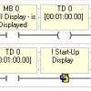
Link a memory bit to your screen 1 (bit is on when this display is on the screen).
Then use this bit as a condition to run 1 minute delay timer and use the direct contact of this timer to load the home screen.
-
I use MODBUS RTU to communicate with third-party devices such as VFD's, power analyzers, etc..
I also use UNICAN for communication between PLC's.
Btw It would be great if Unitronics supported ETHERCAT protocol for the UniStream products!!!
-
1
-
-
Very good job!
-
1
-
-
Geia sou Panagioti,
You need to make sure that the PLC 0V is connected to 0V of your VFD analog input.
If yes, then you might need to isolate the loop via a signal conditioner like the one below:
I had a similar problem in the recent past and i also asked for help in the forum.
The problem was not solved until i replaced the VFD with a new one from another manufacturer!
-
Just another alternative solution..
SB3 (1 Second pulse) is on for 500mS and off for 500mS.
If you "OR" the positive and negative transition contact of SB3 you will get a pulse every 500mS.
-
Geia sou Panagiwti,
I have successfully completed similar applications in the past.
Since the PID process should be based on temperature measurement, your temp. sensor input ( For example a K-type thermocouple) would be the PID process input.
I think the easiest way to control a VFD is to use an analog output.
In the PID configuration, set min PID output register to 0 and max PID output register to 4095 (This is for 12-bit analog output)
Then just run PID process and store the PID result value to your analog output linked register.
In case you choose the analog way, you need to check your VFD's analog input requirements and select PLC hardware that suits your application.
Another option is to use a communication protocol like Modbus RTU but of course you need to make sure that your VFD supports this Feature.
In this case, you set 0 to Min PID output and 500 to Max PID output register (If this is the resolution for 0-50Hz of your VFD) and then write this value to the frequency setting address of your VFD.
In any case, your minimum ouput value might not be 0Hz and maximum value might not be 50Hz.
It depends from the application, i just gave an example.
-
I think that a dedicated positioning expansion module for up to 3 axis would be the best solution.
I posted this on July 2012.
Now we have the EXF-RC15 module and this is one of the reasons that we love Unitronics!!


Life expectancy UID - 0016R
in UniStream: Hardware
Posted
Hello MartinIT,
Unitronics spec sheet for UID - 0016R gives a life expectancy of 100K operations.
Maximum switching current is 2A for resistive load.
To prevent wearing out the outputs, Its strongly recommended to:
- Install a flyback diode across a DC inductive load
- Install an R-C suppressor across AC inductive load
Even miniature general purpose relays, such as Omron G2R series, are producing big voltage spikes when turned off which can seriously damage your output.
In general, when output switching frequency is high, use transistor output instead.