

thecarb
-
Posts
24 -
Joined
-
Last visited
Content Type
Profiles
Forums
Gallery
Events
Blogs
Downloads
Articles
Media Demo
Posts posted by thecarb
-
-
I made something derived from the example "V130_send_strings_in_sequence". I put "SB3 1 sec pulse"s positive transition contact to trigger communication for queries. PLC sends commands and reads answers every 1 second.
-
Joe, Thank you very much for your great help.
-
Yes I made it. The problem was the programming USB cable. When it is connected, PLC doesn't send or receive any data from RS232 (COM1). Now it is working.
But I have some questions. Will there be a problem if program needs to send ON command while PLC is reading temperature values? As PLC will automatically send ON command according to other system parameters, I don't know what will happen if ON command will be triggered while PLC is reading temperatures from the device.
On the other hand, how can I change the ASCII hex to binary? Device sends 4 digit ASCII hex to binary and seperate every bits to 16 different MIs. And also when I tried to add one more send and scan protocol, plc doesn't send and scan the message. It only runs for the first send&scan.
Read Status bits
Command with checksum and carriage return = $STA3504<cr>
Response: $STA,status bits,<crc-16><cr>
T -
I made the connection with Terminal program and it worked normally. I have attached a print screen of it. I just needed to add a $ sign before the command, otherwise it doesn't send the right command. I have also send all commands to set it ON and read the other variables. There was no problem.
I have created a Vision program file. Could you please take a look at it? To RUN the device, I need to send $ON177CF<cr> command to the device from the PLC. So when we touch to the button on the screen, it should send that command to the device.

-
2 hours ago, Joe Tauser said:
You didn't show it, but I'm assuming you're calling your COM INIT and Protocol config with a NO of SB 2. If you call them continually it won't work.
Start by connecting a terminal program on a PC to your device to make sure your strings are right and you get the proper response from it. Then transfer what you've learned to the Protocol block.
I like this one- https://sites.google.com/site/terminalbpp/
Joe T.
Hi Joe,
Actually, COM INIT is connected to a SB2 as a direct contact. As SB2 is active just for 1 cycle, I believe this is right.
If you could take a look at the "Protocol Send" image and the examples of the device, could you say am I doing right?
-
Thanks for your answer, however I have tried different things with examples but couldn't make it right.
@All
Let me explain the connection first.
There is a RJ11 socket on V700 with 6 pins. My device has a DB9 connector but it has just active 3 pins. So I made a connection as attached. V700's DIP switch settings are as factory settings, which is set for RS232. Are these steps right till now?
Device's book says that device doesn't send unsolicited messages, it only responds to commands from a host. And as I wasn't sure that I can send commands, I just tried to send ON command so I could see if I could do that when it starts. I couldn't get any results.
Here is the initializing of COM1 port. Pls see "init.png" file.
Here is the ON command send ladder that I made. Pls see "sendONcommand.png" file.
And please see CommandStructures and CommandsON files for the example and explanation of that Command from the Device's book.
Could you please let me know where am I doing wrong

-
Hi all,
I want to use a V700 and a device which also use RS232 connection protocol. There are some datas that should be read and controlling of ON/OFF status of the device. However, this will be the first time that I will use RS232 communication.
How can I program this?
For example, there is a command that I need to use below. I need to read those values and seperate the temperatures to different MI's. I believe I succeed to initialise communication port but not really sure.
$TEA: Read all temperatures
Command with checksum and carriage return = $TEAA4B9<cr>
Response: $TEA,T1,T2,T3,T4,<crc-16><cr>
-
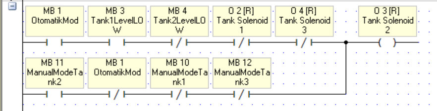
I just added TankLevelLOW inverted contact to the outputs and solved this problem.
@hotwires My question to you is, I will remove that Vector Fill function for normal use, right?
And again thank you very much for your help.
-
Thank you very much for your help, Joe Tauser and your great effort "hotwires".
It works great in "Automatic Mode", except when all the tanks are empty. If they all are empty, it opens all tank outputs but they should be closed at that situation. I tried to add an inverted contact but didn't help. I'm trying to find a solution for it.
-
3 hours ago, Joe Tauser said:
First of all, only put one logical operation per network. When you put several separate rungs in one network, it may not compile the way you think it will. Creating a new network guarantees separation of operations.
It is also very helpful in troubleshooting to keep your functionality together. For example, the timers controlling the fan were spread across several networks. I grouped them together and wrote simpler timer pair logic in the Outputs subroutine.
Timers reset themselves when power is removed. You don't need separate logic to reset them.
I put together a state machine that steps through the tanks in order in automatic mode. I also moved the scaling and the alarms to their own subroutine.
You'll notice that the Main routine is now very small. I put all the functions of the system into their own subroutine. I hate the phrase "best practices", but this way really does make it easier to understand what's going on.
Let me know if it works the way you want it to. "Likes" are always appreciated.
Joe T.
Hi Joe,
Thanks for your effort. However, when I turn on Automatic Mode, it opens all outputs. Tanks empty/full situations are not applicable.
Thanks for your effort. However,
-
2 hours ago, Joe Tauser said:
You've built a bit-banger to make a conditional sequencer. There is a better way.
It's also much clearer to put the outputs in their own subroutine and handle automatic and manual control separately.
Can you post your actual PLC program? I could hack on it for you.
Joe T.
Hi Joe,
I have uploaded the file to "WeTransfer" folder. Please find it attached.
Thanks in advance.
-
hi guys,
is there anybody to help me?
thanks in advance.
-
19 minutes ago, Flex727 said:
It would help to see the rest of your code, but clearly as soon as MB 3 turns off, O 2 will turn on. You will need logic that is a bit more complex to handle your objective. I would set up something akin to a State Machine where you have bits that are Set and Reset according to which tank is the active tank with logic that switches them according to your needs.
Additional comments:
1) You should use a Positive Transition of MB 1 to Reset MB 10, MB 11, & MB 12 and place that in a separate rung from the rest of the O 2 coil logic.
2) Do NOT place separate logic threads in the same ladder rung. The thread with SB 1 - MB 16 - TD 2 should be in a separate rung (and you do not need SB 1 there).
3) You do not need the inverted contact of MB 1 after MB 10 - they are already mutually exclusive.
4) Need more details of how you switch between Automatic and Manual modes. As shown above, it is impossible for logic to switch out of automatic mode (see #1 above).
Hi Flex727,
Please see my answers below.
1) I want anybody to use ManualMode when AutomaticMode is active. If I use a positive transition, somebody can open Manual Mode when Automatic Mode is active.
2) That thread is a part of another logic, I didn't see a problem on placing it in a ladder, but if you say that will cause issues, I can move it to another ladder.
3) This is the same as #1. These inverted contacts restricts switching between automatic/manual mode.
4) If Automatic Mode is active, you cannot use Manual mode.
There are also some other threads in different ladders for the other 2 tanks.

-
Hi all,
I'm working on a project, where we use Vision V570 and V200-E1B. I wrote some codes in order to automize the switching of 3 tanks regarding their level. I wrote something like below. Here is the logic;
When operator resets the situation of the tank, tank status turns to full, when tanks pressure goes below a certain level, its status goes to "empty" and PLC switches to the other full tanks. The problem is, if I reset first tank's status when second or third tank is working, it switches directly to the first tank, before waiting that active tank to be empty. So this causes some tanks stays unused.
How can we fix this? PLC should wait the active tank to be empty and after that it should switch to the other one.
Thanks in advance for your help.

-
On 5/25/2017 at 4:28 PM, Flex727 said:
Do you mean 0-20 mA or 0-10 V?
I mean 0 - 20 mili V.
On 5/25/2017 at 5:49 PM, Joesteva said:The resolution shouldn't be a problem, did you configure the input to be 0-10V? the resolution will only affect your measurement by making it more or less precise depending on the case. Try measuring the output of the Oxygen transducer, since its 0-10V you can just put the probes on the Analog Module.
Yes I configured the input as 0-10 V.
7 hours ago, Simon said:As above, the resolution will not prevent you from getting a reading. You mention 2-wire transducers. Firstly just work with the Oxygen transducer, as I assume it is a 3 or 4 wire device? I would expect the Jazz to read it fine. If you are including the 2-wire devices in the IO wiring they may be interfering with the readings.
Also when you say you "couldn't get the measurement" what does that mean exactly? Was the value 0, 1024, 32767? Did it vary at all when the oxygen level varied, even if it was the incorrect value?
With the 2-wire devices, the Unitronics PLCs do not provide loop power for 2-wire analogue transmitters. You will need a power supply for loop power and the best way to do this is to use an isolation module with loop power capability.
Oxygen transducer has 2 wires, so you don't need to feed this, it gives 0-20 mV output according to O2 composition. As we have sold that sytem with Jazz PLC, I don't have the chance to try it. The value was "0" when I connect oxygen transducer with other 4-20 mA pressure transmitters.
-
Hi all,
I have a project, where I need 2 x 4-20 mA (2-wire) pressure transmitter and 1 oxygen transducer with 0-20 mV output.
In the past, I tried to use that oygen transducer with Vision V570 and V200-18-E3XB snap-in I/O. We have succesfully read the input with that configuration. However, last week I tried to connect that oxygen transducer to a Jazz JZ20-T18 alongside with 2 x 4-20 mA pressure transmitter and we couldn't get the measurement from that oxygen transducer. I don't know what the problem really is but I thought that the resolution or the un-isolated inputs can be the problem(s). Jazz has 10 bit, un-isolated inputs and Vision has 14 bit isolated ones.
Which PLC model should I use? We need touch-screen display and a model with a lower price would be better, of course if it is possible.
Thanks in advance.
-
Thanks all for your response. I used a subtract function and high filtering but didn't really help.
Thanks for the example but I couldn't really get the concept of the second net. When tank pressure is equal or below set point, MB0 energized. And when MB0 energized, Output 0 is not energized.
-
Hi there!
I am using on a project and one part of it is filling a tank to a specified pressure and then giving an audible alarm. Pressure value will be added from the PLC, and then when the tank connected to the pneumatic line of the device, it will fill the tank to the specified pressure. It is very similar to the tyre inflation stations. However, in my program filling solenoid is not very stable and it opens/closes too fast, like 3 times in 2 seconds. What is the best way to program it for a more stable version? I have used a "Compare" function, which compares the actual pressure with the set value and it opens the filling valve.
Thanks in advance.
-
Yes, "bit" was an MI.
I tried to activate the filter from the Hardware configuration but I cannot see the filter section on that screen. I am using V570 and V200-18-E1B. Doesn't have this PLC and I/O filtering?
-
Hi all,
I have a project with an analog input which connected to a level transmitter. If I directly show the input on the screen, it can change 2-3 times in a second as it is not very stable. So I tried to solve it with sampling with a timer.
Timer runs as soon as PLC starts to run. When timer reaches to its "set time", it copies the data on the analog input to a bit and reset itself. On the screen I see the "bit" value. The problem is after some amount of time, lets say 3-4 days, it stops to copying the value and display shows the same value even if the level reaches to full.
What do you think? What am I doing wrong?
Thanks in advance.
-
Thank you very much Alexander.
I think there was a misunderstanding on the ON/OFF control sequence. Yes there is a "." before the numbers and I don't know why but they are not 0.1 seconds and 0.40 seconds. They are 1 and 40 seconds. So I just set the timers to 10 seconds, because when I was testing the program on the PLC, I didn't want to wait too long. Now I can set the correct time for those timers.
-
sure. I attached a screenshot of the nets.
I also tried to put these in subroutines but didn't work well.

-
Hi all,
I have a project and need your help

We have a button which activates MB15. When this MB15 is ON, Output 1,2,3 and 4 should be ON and OFF according to the cycle attached. When MB15 goes OFF, every output should be OFF.
I tried several combination to solve this issue but couldn't make it.
I hope I could explain the situation..
Your helps are highly appreciated.
Thanks in advance.


Double RS232 with V700
in Vision & Samba PLC + HMI Controllers & VisiLogic Software
Posted
Hi all,
I have a new project that I use a v700 and two devices. I could make one RS232 connection with one of them in the past. ( http://forum.unitronics.com/topic/5125-rs232-question/ )
Now I want to connect this V700 with two of these devices. So it will send and receive data from these two devices via RS232. Is it possible to do it? I have used Port 1 for the first one. Can Port 1 and Port 2 be used at the same time together?