AlexUT
-
Posts
846 -
Joined
-
Last visited
-
Days Won
40
Content Type
Profiles
Forums
Gallery
Events
Blogs
Downloads
Articles
Media Demo
Everything posted by AlexUT
-
Quadrature Encoder
AlexUT replied to apbt.drewyoung's topic in Vision & Samba PLC + HMI Controllers & VisiLogic Software
Yes, you can use it in all configurable modes allowed by specification. You have no way to reset counter like in snap-in module. And it will be mapped only to MI. BR. -
Hi Fernando, MI is not a Database, it is a Memoty Integer. There is a backup batery to back up memory content, which include many other data types. As a regular MIs are accessible after power cicle, but some modes of startup/reset will make init for internal memory. So there is no yes or no. Answer is - it may have previous value and may not. You need to know exactly what you need to implement, and there are other methods to save memory registers status. I recommend you to start from some basic things and then go forward. There is a forum topic which partially answers how to learn PLC. http://www.unitronic...sp?TOPIC_ID=527 But I recommend you download VisiLogic from Unitronics web site. It includes free examples and help. And it is free. I will recommend you to download next 2 files from Unitronics site and start to read. http://www.unitronics.com/Data/Uploads/VisiLogic_Software_New/VisiLogic%20-%20Getting_Started.pdf http://www.unitronics.com/Data/Uploads/VisiLogic_Software_New/VisiLogic%20-%20Ladder%20Programming.pdf There is an e-learning link: http://www.unitronics.com/Content.aspx?page=e-Learning I wish you success.

-
Hi Michal, Please provide more information to give you better advice. OPLC model, for example, versions of Windows, VisiLogic, Remote Operator, system software versions. B.R.
-
Moving/Rolling Average
AlexUT replied to Brian's topic in Vision & Samba PLC + HMI Controllers & VisiLogic Software
Hi Brian, Save you value in a separate MI, aside of vector. Then use it when you need. -
Moving/Rolling Average
AlexUT replied to Brian's topic in Vision & Samba PLC + HMI Controllers & VisiLogic Software
Hi, A good idea is to use vector to save values. Then you will use vector fill, vector copy etc. Before adding a last value to vector, shift (n-1) vector values to free space. then calculate average. And do it in cicle. -
how to reset timer in ladder u90?
AlexUT replied to lankasten's topic in Jazz, M91 PLCs and U90Ladder
Hi, No, you do not need to reset it. When the timer's Start & Run Condition is OFF, timer stop counting. When the timer's Start & Run Condition rises again, timer preset loads and timer starts counting. This is equivalent to reset condition. -
visilogix 9.3.1 crashes
AlexUT replied to mikey431's topic in Vision & Samba PLC + HMI Controllers & VisiLogic Software
You need to re-install VisiLogic. There is an instruction: How to re-install VisiLogic Take care to have backup of your project files. -
Timers and flags
AlexUT replied to _GS_'s topic in Vision & Samba PLC + HMI Controllers & VisiLogic Software
Hi, There is a wery good explanation in VisiLogic Help. Open Help, go to Search tab and search for timer. -
Problems with V350-35-R2
AlexUT replied to _GS_'s topic in Vision & Samba PLC + HMI Controllers & VisiLogic Software
Hi Grzegorz, In such a slow working system you really do not need to use Immediate Read/Write. Use direct Contacts and Coils to simplify program. Scan time of V350 is 3-7 mS, dependent of application size and other time consuming operations. B.R. -
Problems with V350-35-R2
AlexUT replied to _GS_'s topic in Vision & Samba PLC + HMI Controllers & VisiLogic Software
Hi, About how Ladder and PLC program works: PLC contineously scan ladder code from up to down and from left to right. All Inputs are read before the start of the first net processing. All Outputs are updated after the last net processing. So at the time you wants to use some Input result - it is already known. Immediate Read operation allowed only for High Speed Inputs. In your case these inputs are 0 to 5. So there are right messages for inputs 6 and up. Now question - why you use Immediate Read? Do you really need this in your first project? -
Energy calculation
AlexUT replied to Brian's topic in Vision & Samba PLC + HMI Controllers & VisiLogic Software
Unitronics OPLCs are supporting complicated formula calculation. Knowing a formula and dependences of formula members from time will allove you to calculate charge/discharge as function of input energy, battery capacity,battery charge level, output load and time. OPLCs have different Time functions to choice from. You will find Formula Element in a VisiLogic Math->Formula menu. -
Easy Question on Interrupts
AlexUT replied to cmarcus's topic in Vision & Samba PLC + HMI Controllers & VisiLogic Software
_Interrupt x.x mS Interrupt Routine start its code even at the middle of the Rung/Net code. And it should be wery short. It works strong at prescribed interval. -
Problem PT1000 temp sensor
AlexUT replied to Hanna's topic in Vision & Samba PLC + HMI Controllers & VisiLogic Software
Hi Hanna, IO-PT4 is a predecessor of IO-PT400 (newest one). Both designed to work with PT100. To work with PT1000, you should use IO-PT4K. This module designed to work with PT1000. -
Problem PT1000 temp sensor
AlexUT replied to Hanna's topic in Vision & Samba PLC + HMI Controllers & VisiLogic Software
Hi Hanna, PT-4x module name used in Hardware Configuration. What module do you use? IO-PT400 or IO-PT4K? PT1000 sensor should be used with IO-PT4K, and PT100 sensor should be used with IO-PT400. If you use PT1000 sensor with an IO-PT400 - it will be a reason of wrong reading. -
10mS Timer Counter problem
AlexUT replied to Andrey's topic in Vision & Samba PLC + HMI Controllers & VisiLogic Software
Andrey, It does not work because you changed DW 1, and logic say that if you want to compare MI 1 to Zero if DW 1 is Zero - it is not Zero already. Attached is other example which works in accordance to your logic rules.
-
Problem PT1000 temp sensor
AlexUT replied to Hanna's topic in Vision & Samba PLC + HMI Controllers & VisiLogic Software
Hanna, It will be better if you describe in more details connection between modules. When you use IO-PT4K, you should use either EX-A1 or EX-A2X Expansion Adapter with a proper cable between it and OPLC. Cables are different. Cable for EX-A1 has Gray connectors. Cable for EX-A2X has Yellow connectors. Connector with a Groung wire should be connected to OPLC. IO-PT4K module should be connected to Expansion Adapter with a cmall flat cable. EX-A1 or EX-A2X Expansion Adapter should pe powered from Power Suply. Please tell if everything i wrote is implemented. -
Problem PT1000 temp sensor
AlexUT replied to Hanna's topic in Vision & Samba PLC + HMI Controllers & VisiLogic Software
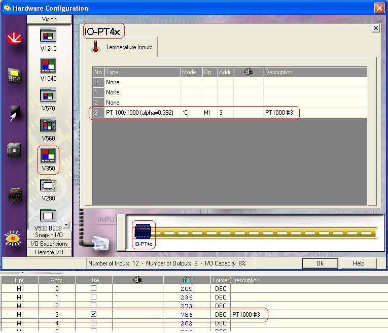
Without adding an IO-PT4x to a Hardware Configuration it will not works. After you selected a snap-in for your V350 - In your case this is a V350-35-R2, you need to click on I/O Expansions, click on IO-PT4x icon, drag and drop it to a rails. *See attached Clicking on it opens a configuration window. Save changes, check connection and test.
-
Problem PT1000 temp sensor
AlexUT replied to Hanna's topic in Vision & Samba PLC + HMI Controllers & VisiLogic Software
Hi Hanna, There are two I/O Expansion modules,I/O Expansion module IO-PT400 for PT100, and I/O Expansion module IO-PT4K for PT1000. In VisiLogic Hardware Configuration there is a common I/O Expansion module IO-PT4X. VisiLogic know to detect which modul is in use. So when you use PT1000, you should use I/O Expansion module IO-PT4K . See attached picture, where I measure a temperature of hot water.
-
Question for V1210
AlexUT replied to Fabios's topic in Vision & Samba PLC + HMI Controllers & VisiLogic Software
Hi Fabios, Answer for second question: Becouse you click "Yes" when asked "Do you want this to be the default Download settings?" when selected "Download All & Burn" or "Burn "Upload Project"". You need to change mode to other one and answer "Not" when asked abiut "default Download settings". Then change mode to "Download" and make it default. -
high speed counter
AlexUT replied to richie's topic in Vision & Samba PLC + HMI Controllers & VisiLogic Software
Hi richie, What OPLC type do you use? Do you use any Snap-in/Expansion Modules? You need to use shaft encoder and set up properly hardware configuration, then then direction of muvement/rotation will be detected automatically and counter will be incremented/decremented in accordance. There are examples you will open from Help Menu -> Examples. -
10mS Timer Counter problem
AlexUT replied to Andrey's topic in Vision & Samba PLC + HMI Controllers & VisiLogic Software
Andrey, I suggest you the next modification. It works and doing everything as you wants.
-
Hi, Please check if you use in a Ladder the same MI for Trend and TC. Check power connection to snap in card. There is no idea without knowing what exactly you are doing.
-
relay outputs will not work
AlexUT replied to richie's topic in Vision & Samba PLC + HMI Controllers & VisiLogic Software
Hi richie, V200-18-EX3B is isolated from OPLC. You need connect power to "24VDC DIGITAL OUTPUTS". Contacts are located right-side under "ANALOG OUTPUTS". Relay starts to work (click). -
Hi Danny, I am sorry for missing your request for help. Was the problem solved or you need further help? * PLC can not answer to any HyperTerminal input as by default it use VisiLogic communication protocol. ** To check cable or adapter, you need to shortcut pins 2 and 3 at 9 pin RS-232 connector. Entering any symbols from HyperTerminal will echo back.
-
Hi Michael, I am sorry for missing your request for help. Was the problem solved or you need further help?