

newbie88
-
Posts
17 -
Joined
-
Last visited
Content Type
Profiles
Forums
Gallery
Events
Blogs
Downloads
Articles
Media Demo
Posts posted by newbie88
-
-
3 hours ago, Ausman said:
Flex is correct. I have often harped on the forum about the way to learn any PLC things, including Visilogic. If you have never worked with a particular function/operation, you should play with an actual plc just experimenting with only that process until you get it exactly right, and fully understand how it works.
You then progressively build your final version, saving under progessively descriptive different names and test along the way. Once an error appears...which it will....!!......you can find what's caused the issue very easily.
cheers, Aus
Ans: Agree. Initially I building one code only and tested successfully before going to the 2nd one however encounter problem. I'm rebuilding the 2nd one with socket2 to test it out before I merge them as one again. See how it goes. Cheers~~!!
Below my testing of the respond times to a wireless device for socket0 only .
https://www.dropbox.com/s/haq72vhmarqqhow/Wireless devices connection.MOV?dl=0
-
13 hours ago, Flex727 said:
The way I troubleshoot this sort of problem is to save the program under a different file name, then delete all the code for the connection that works, then try the other connection to see if it works, and if not, troubleshoot that independently. Compare the part that worked with the part that doesn't work, VERY CAREFULLY. Once you get that working, add back in the code for the other device.
That said, you will get your best help if you post your program file here for us to look at it. Just pictures doesn't help as much.
Ans: Agree. Currently what i'm doing is to remove the faulty one and test and keep the one that is working and rebuilt and re-assign code addressing for the 2nd one again with the working codes. I shall test it individually before merging them as one however today I'm not with my controller. Maybe I will do it tomorrow. Noted with thanks.
Something I realized that only socket0 & socket2 have something to do with Modbus however socket2 seem only allow slave connection and only socket0 can be used as master client. Correct me if i'm wrong. Currently I'm replacing the 2nd one with socket2 so wonder whether visilogic can have two masters or just one? Kindly clear my doubts on the default descriptions from the each sockets. Thanks again.

-
I had separated the two connected blocks however it still no good when I switch my wireless device to IP"39". There were no respond to SB148 . For your information both the logic is identical except the IP and port number is different.

-
6 minutes ago, Joe Tauser said:
Tip - you can hang a subroutine call on the rail. You don't need SB 1 - this is not a Japanese PLC.
Joe T.
Ans: Noted with thanks. ; )
-
10 minutes ago, Joe Tauser said:
No.
It's a little complicated and has to do with who is the Master and who is the Slave.
The port number must be unique to each socket. Port 502 is the industry standard for Modbus IP but you can change that number on the Unitronics side. The port number is local - it took me a while to get my head around this when I first started playing with Modbus IP. Being a certified PLC dinosaur, most of my Modbus experience was with serial RTU where you don't have to worry about such things.
But each Master socket can have a port number totally different than the port number on the device you are talking to. Remember - the port lives on the device. In UnitronicsLand, you can use any port number you want as long as you keep track of them. They're like slots in a massive mailroom.
It looks like the PLC is always the Master in your application. So...
PLC Master Socket 0 Port 502 asks for data from device 1 (socket unknown and not important) Port 502.
PLC Master Socket 1 Port 503 asks for data from device 2 (socket unknown and not important) Port 502.
I know. Clear as mud.
I always ask people to post their code so we can have a look at things you're maybe not showing us.
Joe T.
Ans: I shall try on port 503 for socket1 and separate them into two rungs and remove SB1 to try out. Thank you so much for your advice.~!! cheerzz~~!!
-
9 hours ago, Flex727 said:
The left-most item on your ladder rung with the Socket Initializations and MODBUS Configurations MUST be a Positive Transition contact or SB 2.
Ans: I did inserted a first pass SB2 in front just that it is too long to display the whole ladder

-
3 hours ago, Ausman said:
To add to Flex's comments, you really don't need to cram so much into one ladder rung. Sometimes, although it might look ok on the ladder, things won't work the way you expect due to the way the PLC interprets the info. Splitting areas up into separate rungs often makes a project far easier to work with.
I also note in your socket init rung that you are setting SB168. Do you know about Power Up values? In the operand list you have one column with a power plug. For MBs you can choose none, Reset or Set that occurs on power up. What you are doing does the same thing, but is an awkward way of achieving it.
cheers, Aus
Ans: Thanks for the advice I shall separate that portion into two rungs to try out later. Cheerzz~~!!
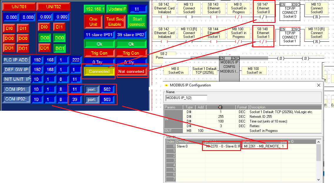
can two different sockets use the same port number 502 for Modbus communication? Seem to me
-
Hi there.. so far my socket0 is working fine when a wireless device is connected to it however I tried to implement socket1 for the same usage so as to concurrently receive data out of two sockets however the 2nd socket1 is not working. Currently i'm testing with the 1 wireless unit ip 10.1.8.11 and switching it IP to the last digit 39 to test for socket1 no matter how many time I triggered, it cannot respond with SB148 on. port number for socket0 502 & socket1 20000. Can any advice on this please??

-
that's great Isakovic~~!! Will try this out~~!! Thanks....
-
39 minutes ago, Flex727 said:
I'm sure you're correct about not needing to reinitialize the FB in normal situations, but I assumed it would be necessary at some point if you have more than 15 slaves. I thought it would be simpler to have a single routine that repeats for each of the 20 slaves. You could do 10 and 10, but I don't think it saves any time as the FB initialization appears to complete in a single PLC scan.
Noted with thanks.
-
Thank you so much for the valuables informations to me. I will try out and see which methods the best to reduce the read out times per unit. Cheerzzz~~!!
-
Hi there.. I'm also using a single socket0 to read out values of 20 slaves unit with individual having an unit IP address last digit 1 to 20 for example? Can i do it by just changing the last digit of an IP address MI2243 . So do i need to close/open socket every time when i'm reading values out of it upon the complete switching? Or i just need to change the IP without toggling the socket at all? How to go about doing it? How long it take for the values to be ready to be read upon the socket reopened? How long do i need to close the socket before i can reopen it again to read the next IP values? Any bit to confirm the values is readable before going to the next one? Any advice from you?
Steps:
1. connect socket
2.Read unit01-192.168.1.1
3. close socket
4. connect socket
5. Read unit02-192.168.1.2
6. close socket
7. connect socket
8. Read unit03-192.168.1.3
''
''
''
9. close socket
10. connect socket
11. Read unit20-192.168.1.20

-
Hi i found a link for an answer for the indirect email text resolved by Ofir Unitronics Support Guru
-
Hi there, i only can find append buffer to SD file instead of user file. Is this the same? By the way visilogic can assign an indirect tags to the "from email", so can unilogic also able to assign an indirect tags account on hmi for user to define himself instead of using a fix one?


-
Hi,
While waiting for an answer i'm choosing list of texts variable to try out. For the first time tagging the type do not show string ascii, second attempt click to edit tag again the string ascii appeared for selection however is with error. Anyone know how to resolve this?

-
Hi,
I need help on how to relate and establish the emails & sms on visilogic into unilogic software using indirect tags.
1. Screen shot 1 showing my visilogic example how i go about using indirect tagging in all required columns.
2. For Screen shot 2 i'm trying to apply the same concepts to unilogic sms having indirect string ascii tagging used for mobile number and texting however it do not allow a second number to added. I need to send 8 numbers for 1 particular alarm triggered. Am i doing this correctly and how to add another number for the same texting?
3. For Screen shot 3 i'm trying to apply the same concepts to unilogic email having 2 email accounts assigned as string ascii for indirect tagging however for the messages texting there isn't an option for string ascii selection. Under the add account section, the "from email address" & "user" do not have an option for indirect tagging. How to assign it as Indirect tagging. Please advice. Thanks.


Reading MODBUS IP as TCP from multiple IP addressis?
in Vision & Samba PLC + HMI Controllers & VisiLogic Software
Posted
Ans: hi all~!! i got both sockets working for two wireless devices~!! Thanks & Cheerzzz~!!! Pls see the link below reading analogue & digital signals.. 😄
https://www.dropbox.com/s/7a10ab5fdqiefnt/Two sockets to two wise devices.MOV?dl=0