JustinCochran
-
Posts
26 -
Joined
-
Last visited


JustinCochran's Achievements
Member (2/4)
0
Reputation
-
So I connected the solenoids to the vt card yesterday. Just for safety precaution I put power to card through a push button in case it tried to move too fast on me. I started by inputting my X on analog output and it works properly. The higher the number faster it moves and same way in the negative. So I wrote the code using the 4 prox switches as stages for a different setting to be stored into analog output and it works great.
-
Yes, I did read that. Thanks for referencing it again though, I hadn't noticed that for future I can use the IO-AI2AO4 module to accomplish this without the analog converter. This is first time I've ever dealt with analog outputs. I've done several analog inputs for leak testers using pressure transducers. I still have much to learn.
-
Just want to update this topic for future reference to anyone else that comes across this or something similiar. Much thanks to Joe for calling and going over some of this and getting me started in right direction. Today I powered up my plc and used an analog output from my snap in module (4-20ma) to the analog input of analog converter box. It was already setup for 4-20ma on converter input. In coding I made X of analog output -100 to 100. I hooked up voltmeter to output of the converter. The output is setup for +/- 10v. While changing my X in program, I could see the voltage move from -10 to 10 on output of converter. I next ran wires from converter to the vt card analog input. Reading a positive voltage of any kind puts 24vdc to one solenoid while a negative voltage energizes other solenoid. I didn't have the solenoids hooked up though, just testing the output on the vt3006 card. That's as far as I got so far. Will do more testing next week.
-
I'm guessing that is what this little relay is. Haven't been able to find much info on it yet. I do know it has a 24vdc power input, 4-20 ma input and a +/- 10v output. The output went to vt card, rest of it wasn't hooked up. I'm drawing a blank on how to even begin the coding for this. Im a fish out of water on this one. Any examples of this type of control or anyone have an idea how to begin?
-
Thanks for the response. I'd like to add that there also is/was an analog relay block that has dip switches set for an input of 4-20ma, and output of +/- 10v. I know the output from this relay went to card. I'm assuming the input came from old plc system. I know I can probably use analog output from my snap on module to input of the relay. Just trying to think how I can code it to work properly. All wires that were on card are still where they went. I have the 24vdc input power, both solenoids to proper terminals, and that one input to card from the output of +/-10v from analog relay block. I have some what of an idea in my head, too hard to explain though. It involves using the 4 prox switches and increments to output. Just for simplicity, my 4 inputs are down, almost down, up, and almost up. I'm also thinking of using 4 of my outputs to control each stage. If anyone has dealt with something similar, I'd appreciate any advice on how to go about this. Thanks.
-
Hey all. I've stared a new project and am giving myself a good headache trying to wrap my brain around this probably simple problem. I have a rexroth vt3006-s-30 card controlling two valves for a hydraulic cylinder to move in and out. Looks like the old plc that wasn't there anymore may have had analog output to rexroth card. Has anyone dealt with rexroth vt3006 cards and controlling them with visilogic? My carriage that cylinder operates has 4 prox switches that I was trying to perhaps use for different stages of where carriage is. Is there perhaps easier way to control valves without the card and using visilogic program to do same thing as the rexroth card? Any thoughts? Thanks for any and all responses.
-
Nevermind I think I have a solution that I'm going to try.
-
Hello, I'm in the process of doing program for a blow molding machine. This one has rexroth vt5006 s16 r1 proportional amplifier cards for molds open and close valves. Used to have a maco 8000 system and I'm installing v1210 visi system. I'm trying to wrap my head around how to properly use cards with plc. Hoping someone might get me started in right direction. Here is what I know. Inputs to plc: Mold open prox, mold partially closed prox, mold close prox, and mold completely closed prox. Outputs from plc to card: Close mold relay on terminal 12c of card, close mold cushion relay on terminal 12a, open mold relay on terminal 16a, and open mold cushion relay on 16c. Outputs from card to solenoids: Open mold sol on terminals 2a and 32a of card, close mold sol on 2c and 32c. The cards are still wired to valves and whatever else is there except for outputs from plc to card, for now anyways. I'm more interested in the logic for controlling them. If anyone can help, I'd appreciate it. Thank you.
-
All my other inputs and outputs on the snap in module are fine. The power supply isn't the issue. On the analog inputs there is the following for each of the 3: V I 0V The 4-20 mA sensor clamps around a motor lead and has a "+" and a "-" connection. I think I may have figured out my problem, will have to check next time I'm at work. What I did was go from the + of sensor and go to V and I of ANI0 and the - to 0V. But I don't have any 24VDC + going to it. I'm thinking I need to have the 24VDC + to + of sensor and then the - to I and V and 0V going with the other commons. Now that I think of it, I forgot to give it power. It's usually always something simple, lol.
-
Something to add. When the motor I have is running or not, it always says -24 on output of the linerization block. The input bit is always 0 on the linerization block.
-
Hi, I'm using a V200-18-E1B and I have an analog input from a 4-20 mA amp gage. The problem I have is the reading I get is always a negative number. Instead of seeing 22 it's -22. I have it set up in linerization where x is 204-1023 and y is 0-100 representing a %. I have a common 0V going to 0V on the analog input. I jumpered V and I together and connected one side of the amp gage to that and the other to the 0V. Am I doing something wrong? I keep looking over the specs and how I configured and I'm drawing a blank. Justin
-
Hello, I recently got a new laptop and I'm trying to save my projects from one laptop to a flash drive, so I can save them to the new one. However, when I try it keeps saying the following: "An open project cannot be saved to a removable storage device such as a disk on key. Once project is complete, it may be copied to such a device." So I guess my question is, how do I make it complete, or how do I get around this? Thanks Justin C
-
VisiLogic Error
JustinCochran replied to wildweasel's topic in Vision & Samba PLC + HMI Controllers & VisiLogic Software
I don't remember if I even put the link to the page I used in my post, since a mod has to approve mine anyways. Just in case I did forget, here it is. http://forum.unitronics.com/index.php?/topic/2517-uni-software-installation-in-windows-8/ -
VisiLogic Error
JustinCochran replied to wildweasel's topic in Vision & Samba PLC + HMI Controllers & VisiLogic Software
I had the same problem and I have vista. Check the link below, I used that way to fix my problem. I didn't have to disable UAC though, I omitted that step and it worked fine for me. I did however have to go to properties and unblock it, and also make it "run as administrator". On my PC the admin user is what I use. Hope that helps. Justin -
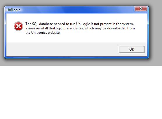
I have tried to intall the unilogics software on my personal PC 4 times, first time I ended up changing the UAC since I use vista. Now it gives me this same message. Each time I uninstall everything and redownload it, then install again. Once it's done and I say yes start unilogics, I get this message. Am I doing something wrong? I downloaded and installed on a laptop that also had vista with no problems.