

Juandiaza
-
Posts
41 -
Joined
-
Last visited
-
Days Won
1
Content Type
Profiles
Forums
Gallery
Events
Blogs
Downloads
Articles
Media Demo
Posts posted by Juandiaza
-
-
I am trying to activate my modem GEMALTO in my Samba 4.3" but I couldn't yet because the provider phone company AT&T ask me what is the IMEI number device and I got this info (See info below).
The sticker device says: CINTERION EHS6T
USB
Barcode: S30960-S2740-A100 (Top Barcode)
357042063006721 (Under barcode) both have 15 digits, I assume that one of this is the IMEI number and tried to activate the SIM card but It won't work, So
Does anybody have an idea which one is IMEI number????
I am living in the US if anybody has a suggestion which provider Can I use for?
I appreciate your help.
Thanks
-
Flex727 and Joe Tauser,
Thank you for taking your time to had helped me. I already figured it out.
You know what It was. I put the logic ladder in lots subroutine in order to organize my sequence but it won't work like that. I put them in Main Routine and now works perfectly.
Now, I am going to pass everything because timer won't work either.
-
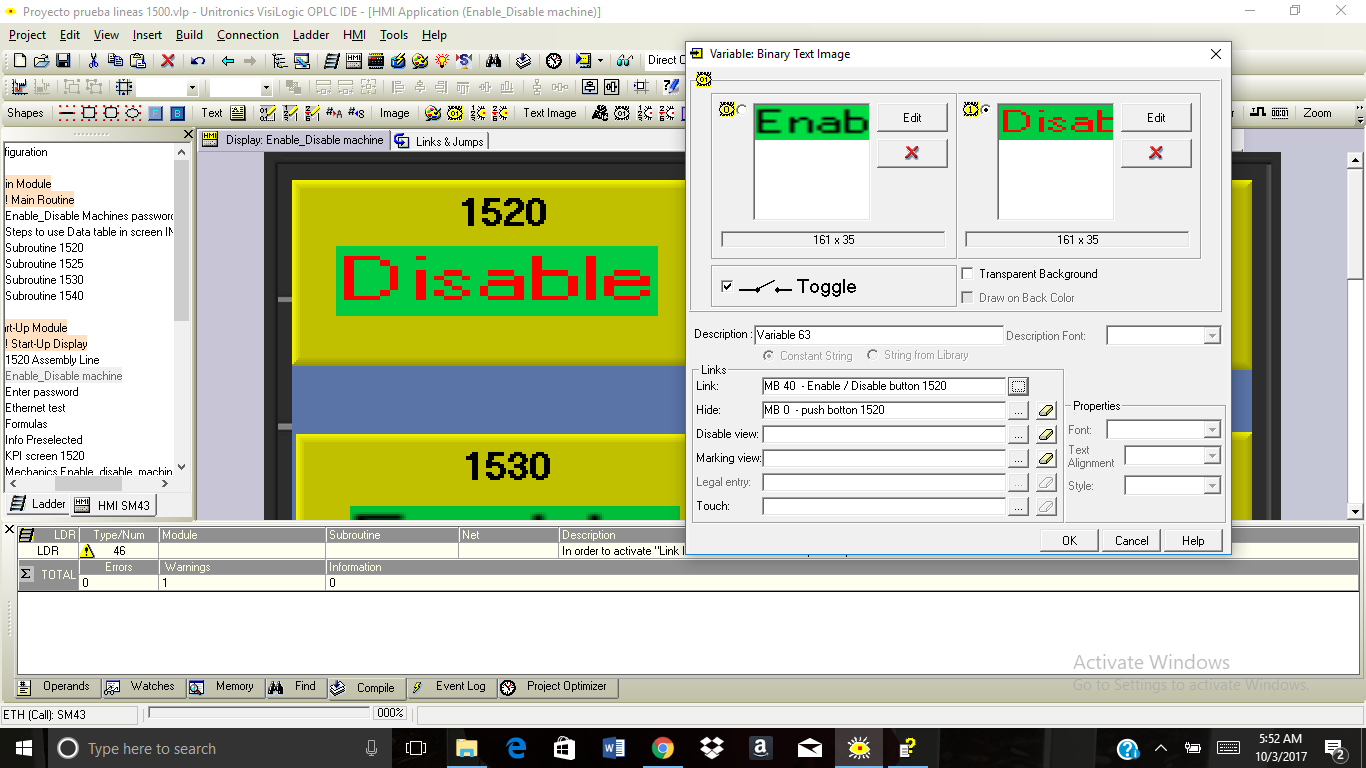
MB 0 is the main button for "1520 Line" you can see it in the first picture on this post in red color. The purpose for this button is once you hit it is able to show to the opartor the Line Assembly (SEE picture next #3) and then allows their report the failure in a specific workstation. I want to hide MB 0 in my HMI if the line is down for some reason through pushbutton MB 40. With respect to Why is my pushbutton assigned to MB 40 because I want to change the state of MB53 once toggle pushbutton is disabled on state "1" .

-
I am trying to change the status of my "Binary image / switch MB 53 (SEE THE FIRST PRT SC "PRINT SCREEN")the little green light under 1520 Line" once you hit a toggle binary Text image / switch you can see it on SECOND PRT SC right after first. But if you notice MB 53 is SET when the machine is Enable and then when you want to reset it because the machine is disabled MB 53 still SET and won't change the status to red on my HMI.
What do you guys recommend me to do over the Ladder in order to SET and RESET MB 53??????????????
Thanks in advanced
(FIRST PRT SC)


\
-
Thank you Cam.
Mine comes with Serial and I installed a Ethernet card. I am going to get the modem and test. I hope will work.
-
Hi, Cam
Yes, I already had the Ethernet card installed. It might work too. It's a good idea.
But let's say in the case to implement SMS like a rule for these events in the company which kit Do I have to buy because I can't see on technical info if both works with Samba PLC or where can I find out this...
Thanks
-
After being installed my Ethernet card on my device. The next level for my project is included Text messages to the mechanics everytime that line's production is down for failures. I would like to programme the logic that allows people call for help to somebody else at the workplace.
First question: Do I need a GSM modem in order to do this????
in case of Yes, I checked the website and found this two models:
Article Description Modems GSM-KIT-16J KIT, MODEM GPRS, CINTERION, BGS2T GSM-KIT-17J-3G KIT, MODEM GPRS, CINTERION, EHS6T I wondering if doesn't matter any of these work with Samba PLC and I assume that I need a SIM card 3G as well or it comes with the KIT??????
Thanks in advance
-
Hey guys, I got a success connection between my PLC and yhe Apps after several times. What I did was get all the info through Command Prompt and use the IPv4s Address in this case was 192.168.0.7 (preferred) and set up on computer and my phone and was able to communicate each other using the same LAN. I tried to connect using different LAN it won't work.
Thanks to all for your useful comments. It help me a lot.
-
Yes, my phone is running on the same subnet?
-
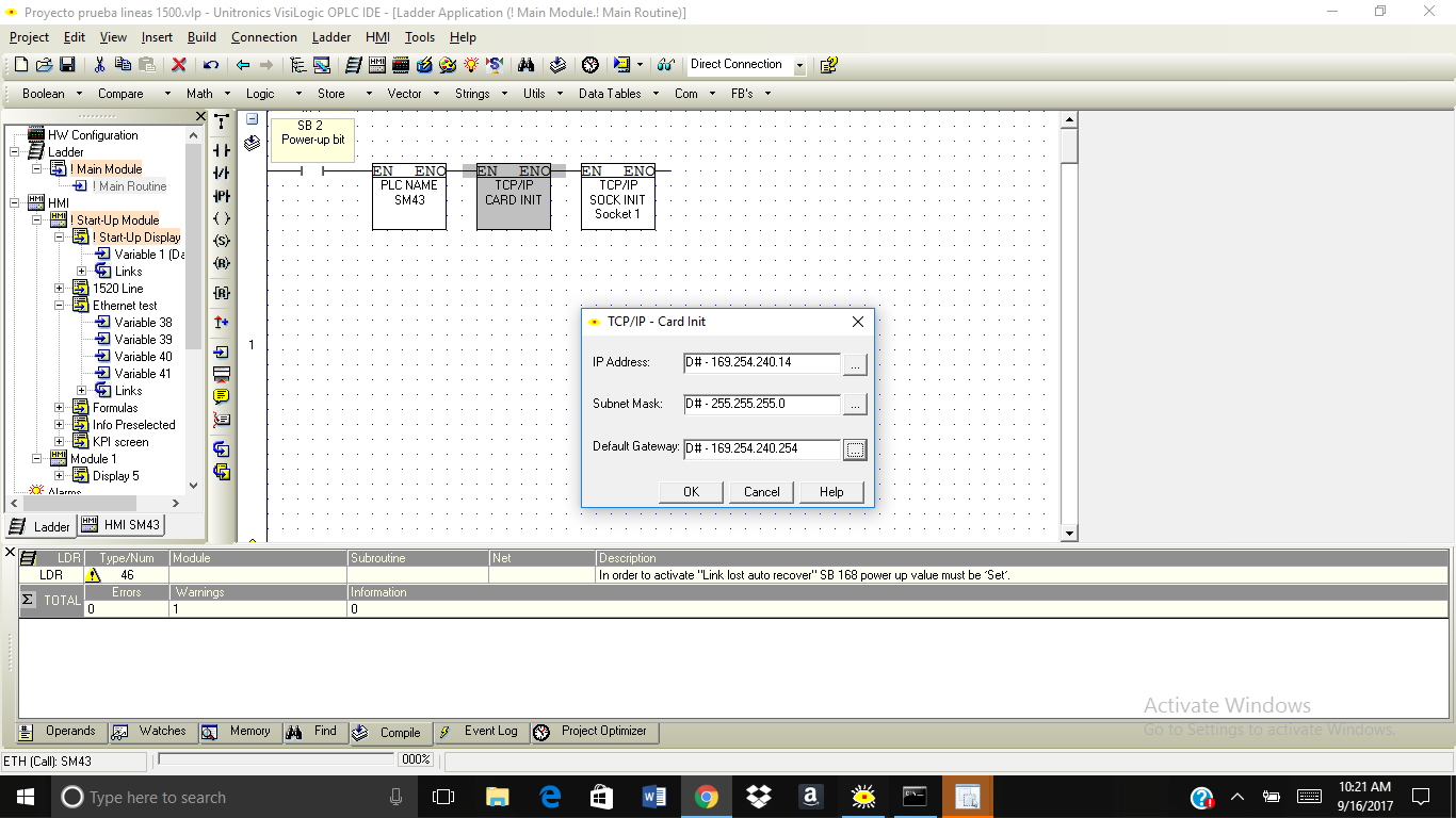
I don't know What I am doing wrong but I can't connect my PLC via Remote Operator. I did it as help said

My IP address is 169.254.240.14

Socket 1 and Port 20256

over the App I set up like this

But when I Check PLC Connection said "Connection to PLC Failed"
Any suggestions for this????????
Thanks in advanced
1-
Drag files here to attach, or choose files...
Max total size 0.98MB - Insert other media
Uploaded Images
image.png
132 kb · Done
image.png
122 kb · Done
image.png
121 kb · Done
-
Drag files here to attach, or choose files...
-
Hey Dan.
I already change the default setting and did what you said and It's working.
Thank you soo much
-
Hi, everyone
I need some help to connect my incremental encoder 600 p/min 24 volts to my project
I'd been trying to connect my encoder in order to read the pulses on my HMI but I don't know how I do that??????
I wire it up as the schematic. The encoder comes with 4 wires Red, Black, Green, and White.
Red = Vcc = here I linked + 24 volts
Black = 0 = here I linked 0 Volts
Green = Phase A = I linked with Input terminal block (I 0 ) as show schematic PLC diagram
White = Phase B = I linked with Input terminal block (I 1 ) as show schematic PLC diagram
My question is If I want to see the pulses over the HMI. How Can I do that?
I know that question might sound pretty easy but I tried with a (variable : numeric) over my HMI but the value doesn't increase or decrease. It keep in 0
Once I can see the value. I would like to make a curve graph to see over it. How to increase and decrease those values.
Thanks
-
Thanks a lot for your help.
-
The model is R20. Is there a way to support if I add any accesories? Thanks
-
Hello, I am new in all of this PLC field but I want to start with small projects in order to get some experience and then moving on bigger projects.
I want to put a graph in my HMI (I actually did it a Variable thermometer Graph MI 12) and see the real temperature value over the graph. According to the Analog Input Wiring, I know that my input (9) AN0 and input (10) AN1 are the inputs. First question: When I start to wire up. Do I just put a wire in AN0 and the other in AN1???? or should be connecting in parallel with V
+ one side and the other side with 0 - references?????And I know that I have to configure this inputs in my HW configuration. in Analog input I put: No. Type Filter Mode Op Addr Description
0 0-10V No filter MI 4 Thermocouple wire +
1 0-10 V No filter MI 5 Thermocouple wire -
Can you guys check if this configuration is Ok? I appreciate the help!!!! I am not sure if I have to link this with MI 4 or MI 5 with the thermometer graph above???
The last question is Do I have to Linearization in my ladder in order to scale values? if Yes, which variable Do I have to attach the linearization?????
Thanks a lot
sorry for mistakes my English is not my first language.


How Can I activate a CINTERION EHS6T modem for use in a Samba 4.3"
in Vision & Samba PLC + HMI Controllers & VisiLogic Software
Posted
What software do you use to run those commands?
because I tried to use PUTTY and hook up the modem to my USB serial port and pops up the screen in order to put the commands on but it didn't allow me even write anything?
I checked the PUTTY software. and reinstalled but it won't work.