

Flex727
-
Posts
3,325 -
Joined
-
Last visited
-
Days Won
241
Content Type
Profiles
Forums
Gallery
Events
Blogs
Downloads
Articles
Media Demo
Everything posted by Flex727
-

Analog 4-20mA input is incorrect
Flex727 replied to vken's topic in Vision & Samba PLC + HMI Controllers & VisiLogic Software
Unitronics publishes specs online for all of their hardware. Just look it up at https://unitronicsplc.com/ -
Analog 4-20mA input is incorrect
Flex727 replied to vken's topic in Vision & Samba PLC + HMI Controllers & VisiLogic Software
I don't think you're understanding how an analog input works. Your analog input has a 10-bit resolution (or 1024 units). The number that you get in the MI associated with the input will range from 0-1023. For 4-20mA, it will range from 204-1023. Use 204 & 1023 in your linearization for X1 & X2 and you'll find it works better. -
V1040Display Problem
Flex727 replied to Neal Jurns's topic in Vision & Samba PLC + HMI Controllers & VisiLogic Software
Do you still have the screen protector film on the HMI screen? If so, remove that and carefully clean the screen. That is not a bootstrap display, that is Information Mode. It appears when the screen is touched for 4 seconds. I have had a particle trapped under the screen protection film that was recognized as a continuous touch. These are resistive touch screens, different from your cell phone (which are capacitive). Resistive touch screens respond to pressure. Make sure there isn't anything touching the screen or torquing it in some way.- 1 reply
-
- 1
-

-
3 Vision 430's Need to share information
Flex727 replied to Lacey's topic in ...I have a project...what hardware do I need?
You're still trying to communicate on every PLC cycle (for 100ms at a time). Try using a positive transition on SB 7 in rung 3 and a negative transition in rung 4. -
Parameter Screen
Flex727 replied to PHoskins's topic in Vision & Samba PLC + HMI Controllers & VisiLogic Software
Make sure the box circled in red is NOT checked when you create your timer.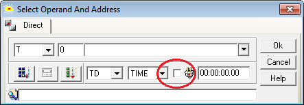
-
Parameter Screen
Flex727 replied to PHoskins's topic in Vision & Samba PLC + HMI Controllers & VisiLogic Software
Insert the Timer Variable onto your HMI screen, select Preset, and check Keypad Entry. You can also select the format you want displayed, a description that shows on the keyboard popup, and other niceties. This will allow you to change the timer preset from your HMI screen.
-
3 Vision 430's Need to share information
Flex727 replied to Lacey's topic in ...I have a project...what hardware do I need?
I don't have time right now to go through all three programs in detail, but at first glance I'll say don't try to communicate on every PLC scan. Put a timer or SB 7 in front of the Read/Write Mixed Data block. There are example programs that came with your VisiLogic installation. Review the ones for MODBUS communications to learn proper technique. -
New laptop specs
Flex727 replied to Flex727's topic in Vision & Samba PLC + HMI Controllers & VisiLogic Software
Thanks, Joe. -
Serial to WiFi Adapter
Flex727 replied to tmoulder's topic in Vision & Samba PLC + HMI Controllers & VisiLogic Software
The V700 is only about half an inch wider than a V570 and is nearly the exact same height (at least from a cutout standpoint). -
3 Vision 430's Need to share information
Flex727 replied to Lacey's topic in ...I have a project...what hardware do I need?
MODBUS command #1 is Read Coils. Coils are MBs. Also, look into "Read/Write Mixed Data". It is unique to data exchange between Unitronics PLCs and is usually the simplest solution for exchanging data via MODBUS. -
Analog input programs
Flex727 replied to alagbawale's topic in Vision & Samba PLC + HMI Controllers & VisiLogic Software
There are lots of examples that came with your VisiLogic installation. Take a look at them at Help/Examples... -
Analog input programs
Flex727 replied to alagbawale's topic in Vision & Samba PLC + HMI Controllers & VisiLogic Software
Items of note: - There are no subroutine calls. - You are still unnecessarily combining too much logic into a single ladder rung. - Your alarm comparisons should be "</=" or ">/=" instead of just "=", and perhaps should be latched. - You have multiple instances of comparison blocks with no coil following, so they do nothing. -
New laptop specs
Flex727 replied to Flex727's topic in Vision & Samba PLC + HMI Controllers & VisiLogic Software
I'll bump this once since it fell off the front page with no responses. Anyone with any inside knowledge of the best specs for the latest version of VisiLogic? -
By the way, I should have also mentioned that, for a self-taught newbie, your program was far better than I'm used to seeing from beginners - certainly better than the first stuff I did (which makes me cringe when I look back at it ).
-
The most glaring thing to me is placing multiple logic threads in a a single ladder rung (Password Entry routine rungs 1, 2, & 5). DO NOT DO THAT! It may work, but it is extremely poor practice and will often not perform as expected. You will not run out of ladder rungs, so break all logic into simple components, one per rung. One other thing is ALWAYS use a positive transition contact for HMI calls. Although the one time you used a direct contact, it appears to me that it will only be on for a single PLC cycle, so it's okay in this case. I didn't dive into the logic itself, but nothing jumped out at me when I reviewed it. In general, when I write a program I only have two things in the Main Routine - Power-Ups then subroutine calls. Everything else is handled in subroutines. I'll try to take a look in more detail later.
-
Analog input linearization issue
Flex727 replied to Sree's topic in Vision & Samba PLC + HMI Controllers & VisiLogic Software
You are correct. Not sure which spec document I was looking at, but it was clearly the wrong one. X1 & X2 should be 204 & 1023, respectively. If the value of MI 0 is zero, then you should expect to see something close to -167 for MI 1. -
Serial to WiFi Adapter
Flex727 replied to tmoulder's topic in Vision & Samba PLC + HMI Controllers & VisiLogic Software
I've done this quite successfully. I have a V1210 in the field that connects (using MODBUS IP) to about a dozen other PLCs, one at a time, by connecting and disconnecting sequentially. I could do 4 at a time, but I wanted to keep the code simple and there weren't any time constraints. The connect/disconnect/connect process is lengthy (maybe 2-5 seconds), but works reliably. -
Visilogic crashing errors
Flex727 replied to lesmar96's topic in Vision & Samba PLC + HMI Controllers & VisiLogic Software
I recommend contacting Unitronics Support directly at support@unitronics.com, or you can open a support ticket at http://support.unitronics.com/ . Although this forum is hosted by Unitronics, it is a user forum and is mostly populated by other users like you and me. -
Serial to WiFi Adapter
Flex727 replied to tmoulder's topic in Vision & Samba PLC + HMI Controllers & VisiLogic Software
Sounds like what you want is a serial to ethernet adapter. They are readily available, though I've never tried to use one. Did you have wifi before? -
call subroutine
Flex727 replied to PHoskins's topic in Vision & Samba PLC + HMI Controllers & VisiLogic Software
I strongly recommend that you do not do conditional subroutine calls. Write your logic so that the subroutine will always be called continuously. Coils in an uncalled subroutine are in limbo and can give you unexpected results. Under normal circumstances, a well-written program avoids conditional subroutine calls. -
No it does not.
-
Hmmm, What if I.....
Flex727 replied to John_R's topic in Vision & Samba PLC + HMI Controllers & VisiLogic Software
I work with chemical delivery systems every day and we always have a separate relay for the equipment and the PLC. The equipment gets powered down whenever an interlock alarm occurs, but the PLC stays powered on. The EMO on the panel does power down the PLC, as well as the equipment power. This meets strict regulations and you should be able to do what you want to do with no issue. That said, I have to ask, why did you choose an IO-DI16 plus IO-RO16 instead of a single IO-D16A3-RO16, which would be cheaper and use less space on the DIN rail? -
+1 & +1 Both of these items are at the top of my wish list, but I've just about given up hope.
-
List to Text on two screens
Flex727 replied to PHoskins's topic in Vision & Samba PLC + HMI Controllers & VisiLogic Software
Ah, I see what you're saying. Yes, any change to an HMI element affects that one single element only. Similar elements, even copied ones, will be unaffected (as it should be). -
List to Text on two screens
Flex727 replied to PHoskins's topic in Vision & Samba PLC + HMI Controllers & VisiLogic Software
This seems confusing. If the same MI is linked to both, then they will both update. You might want to post your project file so we can have a look at what's going on.


