

Flex727
-
Posts
3,259 -
Joined
-
Last visited
-
Days Won
236
Content Type
Profiles
Forums
Gallery
Events
Blogs
Downloads
Articles
Media Demo
Everything posted by Flex727
-

Logic Problem
Flex727 replied to Nancygogogo's topic in Vision & Samba PLC + HMI Controllers & VisiLogic Software
I think you're not really understanding how coils work. Keep in mind that direct and inverted coils are evaluated on every scan. If you have a direct coil conditional on a direct contact, the coil will turn on when the contact is closed and will turn off when the contact is open (the opposite happens with inverted coils). In other types of computer logic, action is only taken when the condition is satisfied and no action is taken when the condition is not satisfied. This is where Set & Reset coils come in. With a Set coil instead of a direct coil, the coil will turn on when the condition is satisfied and will stay on even if the contact opens. You need to use Set & Reset coils in pairs because if you Set the coil, you can never turn it off without the Reset coil (and vice-versa). Above, you have 3 inverted coils in series with a positive transition contact of timer TD 6. That will NOT work because those outputs (O 0, O 1, O 2) will stay on always except for a single scan when the timer expires, then immediately turn back on. No valve is capable of changing state in a single PLC scan. Those inverted coils should be changed to Reset coils. You will also need Set coils for when you want the valves to open. -
Logic Problem
Flex727 replied to Nancygogogo's topic in Vision & Samba PLC + HMI Controllers & VisiLogic Software
I'm glad to see someone else with this same opinion. I ALWAYS avoid inverted coils. In my case it's because I'm an idiot and get easily confused. -
Logic Problem
Flex727 replied to Nancygogogo's topic in Vision & Samba PLC + HMI Controllers & VisiLogic Software
Yes, with VisiLogic you can place coils in series. I recommend placing the Load HMI function on the next line by itself. Placing a couple of coils in series is okay, but I strongly recommend not loading up a single ladder rung with too much logic else you might get an unexpected result. The AND function is for certain specialized needs to make working with the bits within a register easier. It is NOT for normal bit logic, which is why you can't select MB. Search for "logic" in the help file and you'll find AND there. -
Logic Problem
Flex727 replied to Nancygogogo's topic in Vision & Samba PLC + HMI Controllers & VisiLogic Software
AND logic would look like this: Yours is OR logic. What do you mean by "I cannot choose the MB or O"?
-
I create my own alarm history rather than use the built-in alarms function, but the technique I use for this could be adapted to your needs. When I create my alarm history, I store the date and time in a vector of MIs using the "RTC To ASCII" function. If you grab the data from that vector in a ladder rung that is executed before the RTC To ASCII function, with SB 2, you will have the last date & time stored just before power loss. Grab the data again with SB 2 just after the function and you'll have the power on date & time. This can be done in 3 consecutive ladder rungs if desired.
-
The first action to take with most HMI problems is to download a blank VisiLogic project, Reset & Initialize, then download your project again.
-
Problem with logic set or coil
Flex727 replied to Zuku88's topic in Vision & Samba PLC + HMI Controllers & VisiLogic Software
Place a Call Subroutine block in the Main Routine. You can find Call Subroutine under the Utils drop-down menu. -
Sometimes the Snap-In modules can come loose or the contacts can wear in high vibration environments. Try removing the module carefully and replacing it firmly, making sure it's well-seated.
-
I'm sure there are many people on this forum who would like to help, but without any information it's impossible. What method are you using to download - USB, serial, or ethernet? Is this a new PLC and a new program you are downloading? You said "download or upload", which is it? Does this happen every time? Is it a new occurrence - were you previously able to download to this PLC? Can you go online with the PLC? Did you install VisiLogic "As Administrator"? Are you running VisiLogic "As Administrator"? I'm sure someone else will chime in with additional questions - these are quick ones off the top of my head.
-
Problem with logic set or coil
Flex727 replied to Zuku88's topic in Vision & Samba PLC + HMI Controllers & VisiLogic Software
Your logic says either I 48 or MB 48 must turn on to latch O 48. If you are activating either of those bits and O 48 is not coming on then you have one of two things occurring: 1) An O 48 coil is elsewhere in the program and is being turned off, or 2) This logic is in a subroutine and the subroutine is not being called by the Main routine. -
I don’t remember, but I found it on Google.
-
Like Joe said, get into it and if you get stuck, post your code or ask a specific question and someone will be happy to assist. By the way, when I look up "codger" in my online dictionary, there is a photo of guy with glasses and a cigar. Could it be...?
-
I'm sure @Joe Tauser is too modest to jump in here (), but this looks like the perfect subject for the State Machine. You can find his example program here: This may be the best thing (of many!) that he ever taught me. I use it constantly.
-
You're on the right track. Use the "Store Direct" function to assign a value to the MI.
-
Make sure there is only one instance of the "Green Light" coil.
-
What you have should work. Make sure there is only one instance of the "Automode" coil.
-
Do you have power flow all the way to the "Automode" coil when in online mode (i.e. are "Auto_Selector_5", "Stop_2_PB", "Emergency Stop" all closed and "F1_Overload" open)? Is "Start_1_PB closing? Is this in a subroutine? If so, is it being called in the Main Routine?
-
You guys have lost me. I've never seen the communication settings NOT saved with the project. Both the connection type and the project settings are always saved when the project is saved. What am I missing?
-
Maybe my memory is failing me, but I thought that the standard telephone cable (w/RJ11 plug) is wired "reversed" (not exactly like "crossover", but similar), while there is a "data" cable that looks the same that is straight through. The straight through cable will not work for programming Unitronics PLCs, but the reversed standard telephone cable will (at least for Vision). I think the Jazz is different in that it requires the 6 conductor RJ12. I think I slept a few times since the last time I had to use the -CS25 adapter so maybe I've forgotten something. Like Joe, I have a drawer full of them. Unfortunately, now I also have a drawer full of mini-USB cables.
-
That's only for the 0-10V, 0-20mA, & 4-20mA analog inputs. It doesn't apply to thermocouples. Thermocouples have resolution to a tenth of a degree.
-
From the Install Guide for the V200-18-E4XB:

-
Yes, the RS232-CB1 includes the MJ10-22-CS25 adapter.
-
That all looks right except for the D2-DSCBL. That's for Automation Direct, right? A Unitronics programming cable should have been included with your Samba PLC. If you don't have that, I recommend obtaining one from Unitronics or your distributor.
-
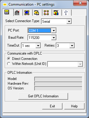
Your Communication screen should look like this for serial communications (replace "COM 1" with the COM Port you are actually using). You do not need the Modem Service. What errors are you seeing? Are you using a native serial port from your computer, a USB-to-serial converter, or a direct USB connection? Most serial connection problems are caused by not having the right serial driver installed on the computer.
-
Are you asking if all outputs can be turned on in one PLC scan even if the ladder is very complicated? The answer is absolutely and necessarily yes. This is true of any PLC.


