

Ausman
-
Posts
2,702 -
Joined
-
Last visited
-
Days Won
189
Content Type
Profiles
Forums
Gallery
Events
Blogs
Downloads
Articles
Media Demo
Posts posted by Ausman
-
-
I'd also look at using a TE timer, which will do it in one hit. But either way, you also need to be setting up a differential around the trigger point, otherwise it will endlessly cycle the alarm as your levels go up and down around trigger point. Sometimes you DO need to over complicate things. One must remember that your student is the dumbest of dumb, yet very obedient. It will always do only what you tell it to.........endlessly! You have to do the thinking for it.
On Timers, if you haven't used them much yet, have a good read of the help files via Index/Timers. Explains well. Ages ago I took a while to get my head around the way Unitronics do them, making them via using Direct Coil was new to me. Also that they only have 3 types.
cheers,
Aus
-
 1
1
-
-
Thumbwheels? I still use them for multiple input definitions on non-HMI plcs! Are we talking the same thing? You Yankees and yer funny words!
cheers, Aus
-
Most actuators, even when modulating, dont mind working in tiny increments, that's what they're designed to do. But I don't understand your maths of 20 x 5 seconds = 1 minute. ?? Lots of start stop will generally mean similar movement to one long run.
The only way you're going to know where it physically is, is to fit the switches at least. Then to minimise the total checking time, force the valve whichever direction is theoretically closest to either switch until it trips. Then go the other way until the other one trips to measure things. And by "trip" I mean the change of switch state depending on which way you have it set up. From open to closed, or vice versa. And my point about valve running direction is important, due to the hysteresis ("deadband") inherent in switches. If you are running the valve one way the switch might change state at 48%, but if you are running it the other way the same switch might change back at 50%.
And I'd theorise that Isak has answered you on the pulse question already but it hasn't appeared online yet. Wait.
cheers,
Aus
-
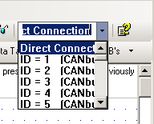
Hi all, something not quite right in the comms dropdown box. I recently moved up to 9.8.31/0 and all seems ok but the dropdown functions oddly. The characters become much larger during selection, and I can also edit them. I thought this might have been a fix of something I requested a while back, but the edit doesn't persist.
Also, sometimes I can only get Direct Connection showing, the drop down doesn't work at all. The only thing I have as a pointer is that it seems to be related to opening something new, or opening after not finding a file where it used to be. You close and restart and the issue goes away. And an edit: I initially attached .bmps to this post, but they don't display as part of the post...just a link. Changed them to jpgs and they do. ??
cheers, Aus

-
1
-
-
I agree with go for serial. The extra cost of a dedicated panel like Cam suggests is often a far cheaper and better system than all the stuffing around and extra outputs needed for driving things directly. Been there, done that. In the old days I actually had to make the array from individual digits!! Aahhh..how I miss that....not! These days, youngsters are so spoilt!
cheers,
Aus
-
1
-
-
15 hours ago, vamalgise said:
The problem i faced was the difference between nominal actuating time (8mm/s, with 40mm nominal stroke=320s) and actual actuating time, which appeared to be more than that.
Hi Vamal, welcome to the real world where specifications differ from actual operating conditions. Even the temperature of the medium alters running times on these things...and load conditions always mean there are varying degrees of flow resistance throughout the circuit. We've discussed this a bit and you could try the alternative method of timed pulses.
But it also sounds like you have been completely relying on the virtual position. You need to periodically force the valve to a physical endpoint and then resume your normal process. And you could build things into your program that check for unusual numbers and self-correct if necessary.
A possible alternative is to implement the 2 DIs and have them not set for endpoints, but measure them between a much smaller span more often. This wouldn't necessarily affect the output much if you set them close to the normal operational span, it would only take a minute or so to do. Then adjust your MAX according to whatever the maths works out to be. The bonus of this method is that you might get one of the DI tripping during your normal operation, which gives you a confirmation of where the valve is physically. and an edit: don't forget that the switches trip at different points depending on which way the valve is running.
cheers,
Aus
-
Thanks Cara, I understand the reasoning.
To get around the "outdated" issue, I would think it would be easy for your super programmers to come up with a little script that could accompany said Library, or even incorporate a "check for updates" button that could be included in the startup folders. Those who download it could then routinely run the check, and it could check all the documents in the local file and just update the ones that have changed. I use the library as my "ready reference" system and it is a great thing.
cheers,
Aus
-
1
-
-
Hi mkc,
Without knowing Jazz too much, only M91s, 2 comments:
1). Why 2 stop bits instead of the standard 1?
2). Given that the problem plcs are the new ones, perhaps you should use Controller/Operating System to check that all the Jazz's are using the same OS. If the newer ones are a later OS, that might be the issue. If they are, the easiest solution might be to match their OS to the older ones, rather than changing ALL of the oldies to new.
cheers, Aus
-
Everything Joe says, and I'd also be having them go over all their earth connections and clean them up/check resistance. The 2 years ok place reeks of something slowly drifting off ideal and your locations imply dirty environments.
On 04/02/2017 at 3:19 PM, active said:Only happens to MI that are either keypad entry or used to manipulate data in the program.
So all the other MIs stay ok? That is a strange thing. Do they do it when adjustments are being made or just whenever? Have you tried disconnect/reconnect all the ribbon connections in the plc system, too? Even internal ones etc? Is the front membrane still ok?
cheers, Aus
-
Hi Cara, although a little off topic, this thread is a classic example of my whinge here:
Immediate posters have done responses/answered, Visco has answered but because he is not immediate his replies haven't shown for them to consider. So other thoughts have evolved which then look odd when the system suddenly inserts Visco's responses into the thread according to their time of lodge, wherever that is in relation to responses posted immediately. Something really needs to be done about this. It is annoying.
cheers, Aus
-
And now that I've absorbed the other responses from you just showing, I think you should first try the Filter function block like Joe's post says...more info makes the world of difference! If this isn't enough, then you'll have to set up filtering of the output from the filter...ie cascade the filtering. I've had to do this on some sensors I've worked with, ended up using timed vector copies from the filter function output that then got averaged. You can do endless maths, depending on how accurate you want to be. But given the medium is agitated, it's always not going to be perfect.
However, if the material is fairly viscous, is the "wave" only an increase in height near the agitator's edge(s)? If so, you should do your level sense once the agitator is past the read point and the medium is stable, which would always be the "lowest" reading in the constant sensing. You would set up some rolling compares checking the "lowest" point in each "up and down". You'd have this compare happening every scan and then put the output into a filter function block and it would likely turn out very stable. ie Find the low point of the medium each time the blade goes past, and filter this.
PS edit: The compare actions would be done on MI2 before you put it into the linearisation. You may not need any filtering at all given you're only doing 0-100 from such large inputs.
cheers,
Aus
-
Sorry Paul, my abbreviation of Linearisation! And I also see some or your other answers, just delivered due to the "lag in posting" factor for new posters. So the follow on question from your answers is: what type of sensor is it?
cheers,
Aus
-
And another few thoughts,
I've assumed that you have the hardware configuration Mode settings at "Normal", not "Fast". This alters your input numbers range accordingly and might be upsetting things if incorrect.
And for monitoring MI2 like I want, the easiest way is to open the Linz itself without being online. Double left click on the block, and once open you then click on the blue glasses icon at the top of the column and it will go online for just those numbers. Especially useful in your case as it will be fast. The main thing is what MI2 is doing.
cheers, Aus
-
Hi Flex, I thought the same but without knowing the tank's layout details it doesn't really matter, the end result is the same. Visco is probably working around the way the output arrives and got to these number placements by trial and error. I remember the very first time I used Linz I scratched my head for a while. That's why I eventually made my excel with extra naming! It might be an ultrasonic that is at it's highest output when the target is closest. So if it is in the top of the tank looking down, the associations are logical, just his numbers placement into the "wrong" positions is odd. I'd do it your way.
cheers, Aus
-
And also a PS to the above.....your descriptions MI 28-31 in your Linz look a bit confusing. MIs are useful as you can easily adjust them online for input tolerance discrepancy. But your labelling might be confusing you elsewhere? Also, just FYI, if tolerance isn't that important, you can use constants instead of MIs in this situation.
Hmmmmm. I wonder if your inputs are going outside the ranges? Can you monitor and report back what numbers you see for MI2 during operation? There is no max/min control inbuilt into the Linz function. If your input goes under or over, the Linz will keep on going in its conversion, which can create issues. Please advise!
cheers again,
Aus
-
Hi Visco,
bearing in mind everything Joe & Hots suggest, I am puzzled in the first place as to why you are getting the fluctuation you say with innate high filtering. Looking at your Linearisation parameters means you are only trying to display 1 or 2 digits most of the time. Have you found and used my Linz calculator here? It can help at times to visualise expected results.
In your Startup Params post, you mentioned a tank field. Given that you also now say it is a bulk level tank, I can't see how it is changing so quickly that you can't get stable readings over a range which looks like you are doing it as a 0-100 percentage of full. That's a rapidly changing level in a bulk tank! What sort of sensor are you using? Perhaps it is positioned such that it is being affected by your incoming material? This would definitely account for your weird readings. Or perhaps you have MI22 in use somewhere else in the program and it is being written to more than once. Right click anywhere in the MI22 row in the Operands tab, and choose "find". Check out the results.
There are many ways to implement filters which will do your job, but at present I am puzzled as to why you need it in the first place! It also just occurred to me that you should make sure your plc is physically set correctly for 4-20 input, if that is needed on whatever you are using.
cheers,
Aus
-
Hi guys,
I might be mistaken but I think Michal is referring to what was available via "Unitronics_Library.zip". (I may have renamed this!) The last time I downloaded shows as January 2015 and it was around 160Mb. It sets up a folder called Documentation\Manuals & Specs within the main Unitronics program folder, and it has heaps of useful info....all in one hit. The current system only lets you download a particular file for each model or subject....very tedious. Please correct me if I'm wrong.
cheers,
Aus
-
Hi & welcome Antonio,
well done to all on this one, and thanks Antonio for the good responses and also your obvious investigating/learning/efforts prior to posting.
We understand reluctance to post code, but if it is not too secret, it might help. There is a wealth of knowledge here and we all started with our "first PLC ladder program"!!
One other last method to check your entire program....find the person amongst your friends/neighbours who is a total computer klutz, ie even gets confused using a mouse etc. Get them to run though your displays and operations to confirm that it all works as you want it to and is easily understood. If there is ever a way for you to find a sequence issue, or make something easier to follow, this is it. The main reason for this suggestion is to ensure that everything is perfect before you ship it as your "global system". Much easier to fix it before it goes out!
cheers,
Aus
-
Yes, and also a fridge to keep it cool.
Aus
-
1
-
-
I recently upgraded a client's computers with some nice little Lenovos. Perfect, except that they didn't come with any recovery media...you order what/if you want and they deliver as necessary. They say this is to save the planet's resources.....great idea.
Here's the pic of what arrived. Have a good look at the ruler and something else in the pic and you'll understand my exasperation!
cheers,
Aus

-
 1
1
-
-
Hi again Michal,
without knowing UniLogic, I think you could possibly backtrack a bit. Find the max frequency the high speed inputs on the module can achieve, and then go backwards from there with the view to increasing the number of lobes on your shafting that your inductive senses. The aim would be to have the maximum counts per rev from the shaft that remains within the limits that the module can do, and then you can likely set things up via maths to achieve much closer control. Also allow a safety margin on over-revving keeping within the counter limits. You don't want your system being told to go faster when it is in fact already going too fast!! Only you will know this margin.
cheers,
Aus
-
I'd still be looking at changing the network to no parity. On the EBMs it is a case of using their dedicated program with higher permissions than are available to the general user. My understanding is that it sequentially applies "unlock" numbers to certain registers, that then let the parity be changed, then locks it again. This may well be available on the stuff you are using.
As Joe says:
On 21/01/2017 at 4:29 PM, Joe Tauser said:Yes, 9600, 8E1 should work but it doesn't.
cheers,
Aus
-
On 20/01/2017 at 8:04 PM, PeterFukt said:
they can no longer push a button on the HMI to start the unit. It is being locked.
Also wondering that there isn't another master on the network somewhere without realising it?
Aus
-
+1 to Joe's comments on the No parity. I didn't mention this before but I did find your mentioning Even a bit strange.
Nearly all the stuff I use comes with either 19200 or 9600 as default, but always 8,N,1. A lot of it you can't even change the parity from none. The exception is the fans I use from EBM, which arrive as Even. I have been told by them that "Ve are German und knowen besten und this ist the axcepted standarden und I should not changen things and commiten fingerpoken", but like Joe, I always change everything to 9600 8 N 1 and things are stable and work correctly.
I can't definitely answer your questions about combinations, but I think you are faced with needing all of them in your coding. Happy to be told otherwise.
cheers,
Aus


Reuse Socket
in We're Listening...
Posted
Flex says: "allow the few seconds" and I think this is your error. Either implement the stages via timers, or create an incremental counter using compares that does the same thing triggering actions a few seconds apart. You could even perhaps use a drum sequencer for this, but as it's not many steps it's a tossup as to the mechanics of how you do it.
Edit: Forgot to add that it looks like you are doing the close and init in the same scan, which is the likely main cause. I'd trial my "seconds apart" method first, then work backwards. Load up the buffer to your maximum and find the shortest time possible for your system, for what I suggest, that works reliably.
Pls let us know how you go.
cheers,
Aus