kratmel
-
Posts
1,148 -
Joined
-
Last visited
-
Days Won
52
Content Type
Profiles
Forums
Gallery
Events
Blogs
Downloads
Articles
Media Demo
Everything posted by kratmel
-
Outputs after power failure
kratmel replied to thomas9's topic in Vision & Samba PLC + HMI Controllers & VisiLogic Software
Perhaps the only problem is programmed in PLC logic of work. If we have a cyclic process, then it's easy to go back to the previous state before power is turned off. However, if the power supply turning off can cause uncontrolled events in the system, it is impossible to return to the previous state. It usually causes a complete restart of the system or the operator's intervention needed. P.S. I liked the mechanical "PLCs" installed in old washing machines. Turning off the power did not affect the cycle of work. After turning on the power, all processes continued until the end of the program. An electric motor and a drum with contacts are good "memory registers" that are not erased when switched off. -
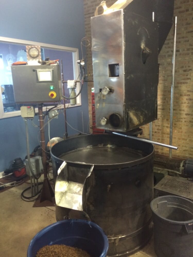
I'm very far from Chicago but the internet is incredible and I "walked" to this place and made a "photo". VFD below control cabinet say - "It is real installation!" Some vintage devices present also :)


-
Setup vs commissioning - a matter of language?
kratmel replied to Cara Bereck Levy's topic in The Lounge
As far as I understand, this concerns the integration of frequency converter control (commisioning) functions into the software. Such software accelerates the commissioning process. Because it is not necessary to keep specialized software on the computer for this purpose. However, it will probably not affect the time of mechanical installation or connection of this type of device. Therefore, I think that these two sentences have different meanings as the JohnR noted. P.S. When I need to compare similar terms, I try to translate them into another language and then do the reverse translation. Sometimes there are quite interesting experiments. -
I have the same issue.. As i see for time keypad entry checkbox is active. Maybe problem is in selected area - checkbox is not active for day and month? This question is to creators.


-
Maybe https://support.unitronics.com/index.php?/selfhelp/view-article/i-updated-my-plc-v570v350-system-files-and-i-had-power-break-down-during-the-download-now-my-plc-has-a-black-screen-how-can-i-recover-the-plc will be helpful.
-
At a time when the optical fiber only appeared in automation, I sometimes must to replace it with a pair of twisted wires as wrote Aus (not even shielded) and the 485 receiver + transmitter. There was also an optical isolation and all this works until today. Now I understand that I did not even think about how fast the connection was. But terminators were needed at both ends of the line. Otherwise there were communication errors that arose when something powerful turned on nearby.
-
MENU >MATH>FLOAT>BASIC>STORE DIRECT (A=B) F function present in ladder
-
It's hard to add something, but the main thing to say is that the V570 panel has an optically isolated port. In my experience, it's important to keep this isolation when creating a longer network link. That is, use a separate power supply and properly ground the cable screen (if present). Many times I additionally put an optical insulator (or use RS485 isolated add-on card) for this network because without the isolation from time to time the drivers of the signal transmitter failed. And the main thing to pay attention to the advice of forum participants
-
It is sound like Watchdog try to restart system. Maybe you must try to remove battery and check it. If U<3V replace it. Try to restart, if not - try to go to info mode.
-
VFD Incorrect CRC
kratmel replied to MartinIT's topic in Vision & Samba PLC + HMI Controllers & VisiLogic Software
What with communication cable shielding? Connected according to the manual? Is it shielded cable used for motor connection? Is it VFD and shielded motor cable correctly grounded? Is it communication OK when VFD is stopped? -
I like flyback diode built-in connector or very close to the coil

-
Samba 3.4 With Lenze i550
kratmel replied to Avik's topic in Vision & Samba PLC + HMI Controllers & VisiLogic Software
You know the maximum engine speed. In the driver, set analog output parameters so that it has 10V when the engine rotates at maximum revolutions per minute (rpm). Next, in the Samba controller, use the linearization block and convert the maximum value of the analog input code to the maximum engine speed you have. See help chapter Linearizing an Analog Input Value. -
Samba 3.4 With Lenze i550
kratmel replied to Avik's topic in Vision & Samba PLC + HMI Controllers & VisiLogic Software
PDO work with fast RAM of the drive. SDO work with EEPROM. It is much slower. I'm not familiar with software used for i550 configuration but you need it for embed needed parameter to PDO message. One question: maybe you do not need CANopen? Samba has two analog input and i550 has two analog outputs. You can configure needed parameter (like speed or current) to 2 analog output and measure it by samba analog input. -
Samba 3.4 With Lenze i550
kratmel replied to Avik's topic in Vision & Samba PLC + HMI Controllers & VisiLogic Software
For run sample you must set on drive CANopen speed and CANopen ID=3 or 4 Samba in 1 rung has ID=1. Sample program send NMT telegram "Start Remote Node" to all nodes configured in CANopen configuration
-
Samba 3.4 With Lenze i550
kratmel replied to Avik's topic in Vision & Samba PLC + HMI Controllers & VisiLogic Software
Example Please read manual for i550 to find CANopen setup https://inverterdrive.com/file/Lenze-i550-45kW-Manual p.186 explaine drive settings. In the default setting, the inverter is configured as slave and waits for the NMT telegram "Start Remote Node" from the master/host system after being switched on. In example present first step that is used for Start-stop remote node. No data transmision - only node activation. Please read Canopen chapter in visilogic help to find how to change slave settings in sample program. You must run communication with drive, after that you have to take the next step - configure data transmision. P.S. You have not answered the question in my message. It's hard for me to figure out how to further help you. -
Chemical processes with which I am not very familiar use powerful power supplies. Each of them is now controlled by the Samba installed in a sealed box. Everything that is programmed in it is a mode of operation that varies according to time. The customer's request is to ensure that even a power cut is recorded as an alarm, but only when it exceeds 15 minutes. This is the case in this production that the power supply network often disappears due to weather conditions. However, the automation returns power and this power return process can last longer than the processing technology allows (powerfull generator started). The idea of an uninterrupted power supply is good, however, does not meet the customer's technical requirements. It should be kept in mind that turning off the power of the process may be caused by an accidental operator mistake to . I am also surprised by the customers' task - but this problem is the last one that I should solve in this order. Thanks to Ausman, Sgull.
-
I'm faced with a task that I can not implement yet. We have a chemical process that is controlled by a PLC (Samba). It lasts more than 24 hours. If the power fails, then it's possible to continue it normally only for 15 minutes without energy. After a switch-off period of more than 15 minutes, the process must be interrupted. It is clear that I need to copy the clock values to the variable every minute, and then, after re-switching on the power, compare the time passed with the value of 15 minutes. The question is how to calculate the shutdown duration, since the real-time clock goes to 00.00 and it is possible that the process can be shut off exactly at 24 hours and no crash will be recorded. I have seen on the forum a way to determine the length if the distance meter is overflowing. If in my case operate time in seconds then may this method work? Of course it is necessary to take into account the change of days in the calendar. Is there an easier way?
-
Samba 3.4 With Lenze i550
kratmel replied to Avik's topic in Vision & Samba PLC + HMI Controllers & VisiLogic Software
Have you ever worked with the CANopen network? Are you familiar with the way how to create messages in the parameters for transmitting information from the frequency converter? Is the converter running alone or already connected to the CANopen network? I have simple examples for control Lenze 8400 drive. However, they need to be modified for your converter. At the same time, you need to study how the device itself is configured and how to change these settings to work through the network. The factory settings are foreseeing the transfer of current speed, but the analog output parameters will need to be manually configured into the message. To begin, I'll attach an example of how to activate the network and set up a network startup via Samba. But it must be consistent with the settings on your device. CAN_test_001.vlp -
Usually I have problems with weight cells only. They failed due to mechanical damage or shock load on the weight device. Did you test the replacement of a module with bad behavior into a good module from a system that works fine? Is it possible that there is a source of electromagnetic interference near the device?
-
I was able to run remote control using the FB protocol. The main problem was to understand how to send bytes in the correct order. I found the solution in the topic - send a stream from MI vector. Below, I show how the message "65" for #15 Modbus power supply has been generated: 111 three bytes of message, 22 checksum. The result in the terminal window is 15 65 1 176 83. I am currently working on programming the power management interface. Thanks again for the help. P.S Checksum in FB Protocol that is used --- CRC-16_B , CRC-16_L - gives the reverse order of bytes in the message (I used 2 bytes of checksum). Format must be Binary


-
Find max, compare with needs and clear max for next measurement cycle

-
I have the same problem with second hand V120. After some manipulation with no result i disconnect the battery for some time. After that i make the hard reset. For V130 it is possible solution By the way i see in visilogic for new vision SB314 bit. This bit lock visilogic communication. In V130 it is no comment for this bit. I do not know it active or not for V130. But it is possible that bit is accidentally set in project and make problem with communication without any note.

-
Even the Visilogic asks for update the settings in the tables. Microsoft does not ask ... it overwrites 💾
-
Thank you Joe Now i have a direction where I need to move. The main thing is to make it possible to switch the power supply to the remote control mode. Now I'm already able to set the parameters, but I need to turn it on and off without using the switch on the front. I think your tip will help and everything will work.
-
Sorry for "links", it is just copy past from msword document (I tryed to make plain text but can not do that - if it possible please correct to plain text). Description of 65-67 user function commands in attached pdf. In txt - copy from online log window on PC for this commands, 68 and 69 do not use by program running on a computer with Win7 OS. I see it in online log window. It used only by manufacturer for power supply modules configuration. RS485 engl.pdf 65_67log.txt