

kratmel
-
Posts
1,148 -
Joined
-
Last visited
-
Days Won
52
Content Type
Profiles
Forums
Gallery
Events
Blogs
Downloads
Articles
Media Demo
Everything posted by kratmel
-
If there are many free relay outputs, I try to do duplicate outputs for responsible tasks. That is, on the same function I use two outputs. Ideally if they are twice as needed. Then, at the time of delivery of the new controller, the user can itself rearrange the wire to the backup output. For simplicity, one of the contacts of two relays with the same functions is connected by a conductor. And accordingly, no reprogramming is required. For inputs I did one backup input which user can enable in parallel with one of any available. But here is the condition that it must be foreseen that this switching takes NC or NO input signal. The same can be done with outputs. JoeT say - solid output +relay on the I/O expansion module with galvanic isolation is the best!
-
error de comunicacion
kratmel replied to meysam's topic in Vision & Samba PLC + HMI Controllers & VisiLogic Software
As we see - it is broken screen on the top left. Sensor on display maybe is "touched by self" - so this screen mode is activate. Or as Flex727 say - it is battery issue. -
One of control box before upgrade, Little Jazz is very helpful in this case.

-
You can use database option for M91 PLC. 1024 MI database present. Sample project - in program help topic. As for me - user can choose stable water amount. Like 0.1L 0.5L 1L 1.5L ect. If you offer to user standart numbers - you can calculate how many user choose each one. And this option do not use a lot of memory. If you has collect amounts of standard water amount, than use simple math = overal whater quantity. And you can download it to U90ladder program like database or see it on display.
-
shaft resolver
kratmel replied to jagaza kenaro's topic in ...I have a project...what hardware do I need?
Direct resolver connection to Unitronics PLС high speed inputs is not possible. Resolver to Digital Converter must be used. Like this: http://www.jvl.dk/files/_2011clean/pdf/ld038gb.pdf -
Better use "POWER LED" :). No fuse needed.

-
Fatal Error
kratmel replied to Emrah AKAY's topic in Vision & Samba PLC + HMI Controllers & VisiLogic Software
Is it flayback diode installed on solenoid cirquit? -
Fatal Error
kratmel replied to Emrah AKAY's topic in Vision & Samba PLC + HMI Controllers & VisiLogic Software
Maybe it is battery issue. Time and date on panel is not current. ??? -
HMI DISPLAY
kratmel replied to Mikel's topic in Vision & Samba PLC + HMI Controllers & VisiLogic Software
Try to build black HMI display with big black flat button without any text. Timer activate black display after no activity. Only problem - you need to save display # to return. Brightness also maybe used in this case. -
Fatal Error
kratmel replied to Emrah AKAY's topic in Vision & Samba PLC + HMI Controllers & VisiLogic Software
I test on V1040 + V200-18-E46B hardware - started with no problem. Maybe problem with sensor configuration or connection. Panel installed on machine or tested separately? Is it any VFD or not suppressed contactor coil present in control box? -
I have a small FM radio with the ability to charge and work from USB power supply. This is my favorite tester for USB chargers and power supplies. The radio has an unpleasant noise when the power is low-quality and as practice shows, all devices that receive power from it also do not want to work properly. It also makes a good indication whether the filter (capacitor) helps to improve the quality of the output power. P.S. Thanks for idea - PLC can now be programmed with the panel door closed over wifi.
-
My HMI not displaying
kratmel replied to alagbawale's topic in Vision & Samba PLC + HMI Controllers & VisiLogic Software
By the way... in future... Do not rename the main display when you start a new project. Never wipe the main display out of the project - this leads to incorrect order of display on the screen. And this can not be fixed by creating a new main display. This feature was studied by my students. After wiping the main display, they were not able to restore the normal sequence of opening display at startup and must to completely redesign the project from an empty project. P.S. In your project this isue not appear. -
My HMI not displaying
kratmel replied to alagbawale's topic in Vision & Samba PLC + HMI Controllers & VisiLogic Software
Please see pic. You do not need to load Main Display. Panel do it for you...:) Another display call please set transition contact (see pic)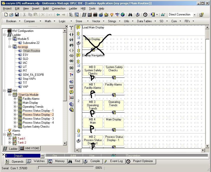
-
My HMI not displaying
kratmel replied to alagbawale's topic in Vision & Samba PLC + HMI Controllers & VisiLogic Software
1-st - load to panel empfy project. 2 - find and load project for V1040 from example for test the panel hardware. 3 -If display blinking you maybe use for change display direct contact -| |-, but only -|P|- must be used. -
Change analog input for test. Maybe You lost one of them :(. Please post contact supervising cirquit diagram. I found in one of control box diagram with full diagnostic of the sensor contact wires. R1=1600 Ohm, R2=200 Ohm, R3= 400 Ohm, R4=200 Ohm. Zener protect Analog input . Circuit open, or high voltage present U input >= 9V, upper wire short to GND U input = 2.6V, bottom wire short to GND U input = 6.5V Normal contact open U input = 8V. Normal contact close U input = 4.8V. You can mount R2 and R3 (or R2 and R4) on sensor side and make protection for shorted and cutted cable. P.S. You must set short delay after signal is changing for correct error evaluation. P.S.PS. Maybe use 4-20mA analog input is better solution...

-
Element/FB scan times
kratmel replied to Ausman's topic in Vision & Samba PLC + HMI Controllers & VisiLogic Software
Debug function for rung time mesurement... Find in help.
-
To solve a problem similar to yours, I used 1 input and alternatively connected various sources to it for analysis. In my case, there were a few free relay outputs and I used them to connect various alarm signals. This option is good for slow processes. Therefore, having analyzed the problem I have created a program in which the high priority inputs are being surveyed more often than others.
-
Maybe min and max position in system parameters is wrong. Max is in min parameter and min is in max.
-
Please check RX TX signal wire. As i see on pic - crossover cable needed to conect barcode scanner to Jazz. P.S. Now scanner is wired to PC connection and Jazz is the same ready to PC connection --- make cross RX and TX and connect GND!

-
Jazz JZ20-J-R16 connection problem
kratmel replied to joro800's topic in Jazz, M91 PLCs and U90Ladder
Is it Jazz new or used (installed with program)? -
Good news - the solution is found. For the future I advise you to make a detailed description of all the actions done on this object. Make a photo of the nameplate. And even if it's possible (no warranty limitations) to make high-quality photo boards inside the device (new and old defective), as well as photo ( screenshot ) versions of programs and firmware versions. Let's hope that the problems will not be repeated. I always document such cases (my favorite way - to write or print on paper?). It is very helpful in the future. cheers, kratmel
-
Maybe it not usefull... and it is not help.... Is it possible to setup date before this date? I had some issue in CNC machine. Setup date like 00.00.0000 is the solution. But maybe in OPLC it is not possible. P.S. Maybe it is possible teporary connect the OPLC to GSM or GRPS modem, phone (ect. with embedded RTC) for synchronise time/date once on power up (if it needed for application). I'm tryed to find RTC with RS232 but it is not present in one device.
-
I try to make some investigation... In my 1040 (maybe 1210 is the same) is used ST10F276 MCU. I can't find separate RTC chip onboard. But find 32kHz addon oscillator for RTC embedded inside MCU. Maybe RTC in CPU is not powered from BATT when power off.
-
V700 Error
kratmel replied to segal's topic in Vision & Samba PLC + HMI Controllers & VisiLogic Software
Please test "Battery status bit" SB8 in visilogic. If it is 1- battery not OK or it not connected to properly (bended contact). -
I try to make some experiments with RTC on V1040 and V570. MalSnaize - please try: 1) setup RTC in Visilogic by the present time; 2) Stop the PLC by Visilogic. 3) Power off- on. 4) check in system menu RTC time when the PLC stopped -- RTC correct or not? 5) Run Plc - Check RTC. Result?


