

Ausman
-
Posts
2,603 -
Joined
-
Last visited
-
Days Won
177
Content Type
Profiles
Forums
Gallery
Events
Blogs
Downloads
Articles
Media Demo
Everything posted by Ausman
-
 Thoughts entering the brain.......... Unlikely scenario but check......Is the new battery actually OK? Does the status bit change correctly if you put in a dud/leave out? Perhaps the system is power cycling without you noticing, and incorrect battery status is a root cause. Associated with above, what I/Os are you using, and are they all powered/wired correctly, and through fuses etc? Perhaps an error somewhere is causing a big enough dip to repower everything when certain I/Os activate everything they have. cheers, Aus
 -
Hi Paul, Yep, a solenoid valve coil turning off will definitely do a big spike. Have a read of this topic for a lot of tips, particularly Joe's post at the end re diode type. Important.......I'm assuming that when you say the noise is coming from coil, you are actually saying it is when it turns off. If it is happening all the time there is an issue with the coil itself. There should be no noise if it is in either state......only on transition from on to off. If there is noise during on, then it may also be the valve itself not opening correctly, but is most likely a faulty connection there somewhere. Check connections etc and try a new coil if possible. Also make sure the code is not written incorrectly and rapidly cycling the output, giving the impression it is always on but it really is going on an off. Put the scope on the line direct during on to check this. Very unlikely but possible. As for how to drive it, for a solenoid valve I would never be driving it direct from the snap-in. The only things I drive direct are very low power things without any inductive qualities at all, like LEDs. Every other instance goes through a standard relay or SSR, depending on the load being driven and frequency of switching. Lastly, my Confucius bit of the post....we all learn something new every day. Sometimes it annoys immensely, especially when it is fixing work by others who should know better. In this case it sounds like the entire machine was built without any thought about noise at all. cheers, Aus
-
Going on the previous photos, I would also consider putting a suitable filter onto the mains supplying all the control gear power sources. And I still don't like that contactor being so close to the power supply and associated wiring. Separate that all out as much as possible, even put the contactor elsewhere. If they are happy to be buying new gear, then get metal enclosures as well! Nowhere near the cost of the plc, but admittedly a bit of mucking around rerouting all the wiring and possibly the component layout. But gee...plastic enclosures and a vfd? Arggh! Get 2 x s/s with one for power gear and one for all controls. I routinely have NO mains in the PLC enclosure at all, only control voltages, with the 24vdc supply coming in to the fuse distribution totally separated from control lines. Probably overkill, but makes it far safer as well as reducing noise issues...which I've never had. Hmmmmm! Finally, it looks like some of the conduit is in Flextite or similar. I'd be earthing one end of this as well, if it is indeed metal spiral. Everything that can induce noise but can be earthed down as a shield should be done. As for the degraded theory....perhaps....but I would have thought it would play up from the word go. Have you reinstalled everything into the plc? cheers, Aus
-
Not even "Roll Back Driver" on the particular port's properties Driver tab, just in case it is that simple? cheers, Aus
-
HI Saragini, You are way more knowledgable than me on this stuff, but just wondering whether your problems might be the "Msoft again taking charge of driver updating" ones that have beset me in the past, and they have suddenly changed a driver to one that doesn't work correctly. I routinely find my choice of "NO" button under Control Panel/System/Advanced system settings/Hardware tab/ Device Installation Settings is changed to Yes, which then allows them to change drivers that worked ok, to ones that don't. It might be worth checking this out, perhaps even via a restore point if possible. Edit: or perhaps even just simply rolling back the port driver as an initial trial? cheers, Aus.
-
VisiLogic and Windows 10
Ausman replied to Flex727's topic in Vision & Samba PLC + HMI Controllers & VisiLogic Software
I am wondering whether everyone's sudden failure issues are related to Win10 again taking over driver updating without you knowing. I check this regularly and it is often turned back on. In my mind it should stick, but Msoft obviously disagrees with that opinion. It might explain why things suddenly change on you. If you don't know the means to turn it off, here it is again: Control Panel/System/Advanced system settings/Hardware tab/ Device Installation Settings/click NO etc. cheers, Aus -
That's great Paul, Hope it stays up. I also hope you hammered those fundamentals into the client's brainstrust with a mighty big stick. So.................now for the sharing of the fee.............!!!! Cheers, Aus
-
Filtr pt 100
Ausman replied to swpec's topic in Vision & Samba PLC + HMI Controllers & VisiLogic Software
This question is really a bit too broad. Please have a read through the Help files using your questions as the basis for looking at the index, and also look at some examples which are accessed next line down under Help. Once you have worked on developing your solutions, post again if necessary, with more detailed questions. Aus -
RTC Problem
Ausman replied to russedwards's topic in Vision & Samba PLC + HMI Controllers & VisiLogic Software
Hi again Wim, I haven't looked at your programs yet. It is important to answer this..... as I have previously asked, have you reinstalled everything relating to the plc's O/S? cheers, Aus -
Hi Ofer, have a look at this post: Try the complete uninstall, do the careful registry cleanout with CC etc and try again. If you can, do a quick partition copy to get you back to your exact starting point if necessary, rather than a restore point etc. See how you go. cheers, Aus
-
PT 100 temp probe ladder and HMI on Jazz Programming
Ausman replied to Paul R's topic in Jazz, M91 PLCs and U90Ladder
HI Paul, pls have a look at the "Linearization of two inputs" example found either via Help, or directly via C:\Program Files\Unitronics\Unitronics U90 Ladder\Examples\Flow, totalizing and pump control. cheers, Aus -
I'm sure it will. Thanks for the solution. If it works and ain't broken, don't touch it! cheers, Aus
-
It would perhaps be a good exercise to log the speed of the VFD somehow. With the plc getting the fatal error I don't know whether doing it into MIs will be held for perusal on cranking it up again, though. But my thinking is that perhaps a particular speed is causing Flex's vibration, or the other thoughts about noise. I routinely wiggle-then-re-gaffer-tape snapins I use, just to keep contacts working ok. Screws sound good. Lots of possibilities here, look forward to the solutions! You're going to have soooo muuuuch funnnnn! cheers, Aus
-
Photos are useful things. +1 to everything Joe says....I was thinking that was a bit further down the track. If these are plastic enclosures, and looking at the general layout and size of the VFD, everything is still way too close together for my liking. A few more comments. The expansion cable being a long one must be one of the cables coming out of the bottom.....and likely into the same cable duct the vfd wiring is in. Can this be separated out into it's own run? And where is the other end located? Right next to the pump??? In another plastic box??? Hmmm!!! It looks like there will be other control gear in the enclosure with the isolator on it. If this is so, then perhaps a neat earthed metal plate b/n it and the plc enclosure would help. It could also be folded and shaped to go around the bottom of the plc box as well for better protection from the VFD. Alternatively, change the plc's enclosure to metal! And perhaps...the VFD might not be the real issue....it might be a big contactor banging on, which if in this enclosure is right next to the plc. Or a combo of both things. All control wiring should be separated out as much as possible. If there is any in a duct that the vfd uses, change it. The only time I've had to have a VFD in the same enclosure as the control gear, I made special shielding plates to essentially have the drive in an enclosure within the enclosure, and wiring was totally separate. Have had no trouble with this. Analog in correctly shielded cable and run on it's own. Joe's "looks like crap" filtering ideas could perhaps be tried if, after fixing the more obvious layout errors, you still get lockups. As he says, put a scope on it and see, but perhaps try all the other solutions first. Proper layout preventing the noise in the first place is far better. Scope before and after basic layout changes would be useful, and show the client something tangible as well. Lastly, is the motor on the pump one specifically designed for VFD running? Something else to consider. cheers, Aus
-
Is the VFD, or any of it's controlling contactors etc apart from signal switching, in any plc component enclosure at all? Where's the expansion cable running? Aus
-
Hi Isakovic, I'm wondering SB167 & particularly SB168 might be affecting this, and also whether one can manipulate them repeatedly? I only ever set 168 at power up...have never played with altering it during running. cheers, Aus
-
RS485 issues
Ausman replied to rmorella's topic in Vision & Samba PLC + HMI Controllers & VisiLogic Software
So did it work before? Is the program allowing enough buffer time b/n requests? What speeds are you trying to comm at? Ziel defaults into 19200 , 8, even. Slow it up (edit, I just realised how confusing that turn of phrase is! Slow to 9600) and change to none. Changing the slave modules with failed comm ports brings them back on line OK? Could the slaves be at a MTBF? Is correct termination in place only at ends? What is the cable in use for 485? Physically check grounding and commoning points for continuity/voltages during use to determine their connections. Going on my knowledge of Ziel bus stuff, I think you are over-thinking it. See attached scrnshot from a manual, noting the simple wiring shown. Do the comms as plainly as possible, then check other things. Comms/cables may not be the real issue. cheers, Aus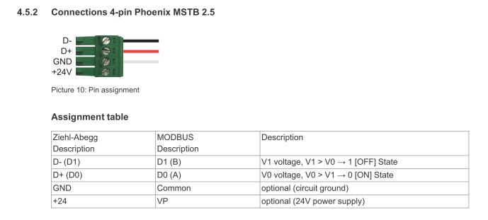
-
RTC Problem
Ausman replied to russedwards's topic in Vision & Samba PLC + HMI Controllers & VisiLogic Software
I don't know the direct answer to this...one of the creators? My thoughts are that it depends on how critical it is. I always try to reduce any operations to only when needed. eg If you have something that only needs to happen once a second, don't run the code until the next second occurs. But if you are talking milliseconds, then I don't see you have any other choice. As for stopping the RTC from working, that's why I would love to see the code. ....but not run it!! Are you there, Wim?? !! And another question Wim. When you get back into seeing the RTC working, is it correct time? Or a delayed version depending how long you have not been able to get it rolling over? If it is correct, then it is working ok....you just aren't being able to read it correctly for some reason. cheers, Aus -
RTC Problem
Ausman replied to russedwards's topic in Vision & Samba PLC + HMI Controllers & VisiLogic Software
Hi Wim and welcome, Stopping the RTC is very unusual!! When you download/run the program that previously worked ok, is it exactly the layout it was before? ie is it an originally saved version, or a modification of the faulty one? It is always a good idea to keep progressive saves of programming work for reasons like this. If it is an original save of the ok version, then do an initialise and reset after download, and then do it again after a power cycle of at least 10 seconds. If it is the "original with RTC problem bits added but then erased" version, again do the initialise/reset/repower after download. It definitely sounds like you have something suspect in your program mods that is still hanging around, but perhaps this might clear it. If no go on all of these, do everything Reuven said. You say you've done the suggestions in the topic, but have you actually reinstalled everything related to the plc's brain? If you don't succeed in any of this, you should post your programs if you can for perusal. Even better would be to send the query to support@unitronics.com. cheers, Aus -
Hey Justin, good news on that. I suppose that you saw this post....? It didn't register with me until the braincells flopped over and shorted today. cheers, Aus
-
I do like this! But when it is in run mode, he is! You're just the schmuck innocently watching what happens! Sometimes my comments begin with "And now the #*$$#!! thing should do xxxx"! cheers, Aus
-
RS485 issues
Ausman replied to rmorella's topic in Vision & Samba PLC + HMI Controllers & VisiLogic Software
Hi rmorella, you don't actually say what your issue is! Does it work at all? etc? How are you communicating with the 430 whilst trying to use the 485 port? Pls describe the issue with more detail. 1). I normally tie it to the earth terminal on the plc, which is tied as close as possible to the chassis ground. 2). Are you saying that you have 0V tied to earth? There are many different views on doing this. But for starters I would only be using the dedicated terminals available for their specifically labelled connection. It is curious that ZA say not to connect the shield...I'm assuming tying it to earth. I guess they are relying on the supposed "self-regulating" nature of 485 to interference. But having the shield connected at one end (PLC) is a must for me. This was discussed here: Also don't forget termination resistors and thus any jumper settings needed on the 430 for this and 485 setting . I have just put a link in a post to the old dedicated communication pdf. Go here, download and have a good read. cheers, Aus -
RS232 data read
Ausman replied to vken's topic in Vision & Samba PLC + HMI Controllers & VisiLogic Software
There used to be a specific communications pdf within the Unitronics documentation download, which I think would be good for you to have. But I can't find it online now. The nearest I get is the online version here https://unitronicsplc.com/Download/SoftwareHelp/VisiLogic_Knowledgebase/VisiLogic.htm And then click on Communication and drill down. The disappearance was discussed in part here: However, I have temporarily attached the old pdf for you to download direct. Will delete it within a few months due to the size limits. cheers, Aus VisiLogic - Communications.pdf -
Hi Justin, Never used one, but although this isn't a specific answer, you perhaps should have a good read of this topic; There are many relevant posts in this topic that might help you out in controlling it directly. However, and this is a big however, quickly looking at the card's specs I think you will be easiest retaining it as the intermediary. You will definitely need to wrap your head around how it works before starting any programming work. Hopefully, others here will have better knowledge of the device, or other ideas. cheers, Aus.
-
FTP Client Issues
Ausman replied to DaveE's topic in Vision & Samba PLC + HMI Controllers & VisiLogic Software
Hmmm. For 3 to be duds would be very annoying! Cara? Does this mean there is a bad batch everyone should be made aware of? cheers, Aus


