

Ausman
-
Posts
2,593 -
Joined
-
Last visited
-
Days Won
175
Content Type
Profiles
Forums
Gallery
Events
Blogs
Downloads
Articles
Media Demo
Everything posted by Ausman
-
I'd also be carefully checking that you have refitted all connections correctly during the battery replacement process. Plugs fully into sockets etc. Or perhaps have broken a wire without it being obvious? If the temp is highly averaged, it might take a while to come back to normal. But in this case I doubt it. cheers, Aus
-
 Thanks Flex, got it, Aus.
 -
Thanks Joe, could you please be a bit more specific as to where this help file is? Looking hard and can't find it, even on search. 9.8.31 Always want to learn something new. cheers, Aus.
-
V350 sms configuration issue
Ausman replied to vamalgise's topic in Vision & Samba PLC + HMI Controllers & VisiLogic Software
And the answer about the OS question is.............????? Anyone?? cheers, Aus -
cannot communicate with the plc
Ausman replied to moises's topic in Vision & Samba PLC + HMI Controllers & VisiLogic Software
Hi Moises, I'm assuming that you are trying to use SD Card Explorer? I don't know 1040s, but I am intrigued why you are using 485. Can you please supply a screenshot of the communications settings window that works ok on the notebook? And does the 1040 have ethernet fitted? cheers, Aus -
Quickly looking at the KA200 specs, I say yes. I haven't done it, but someone else here may have or done similar, and can shed more light immediately for you without me having to delve deeply. I'll wait a bit for more knowledgable info to hopefully pop up. cheers, Aus
-
Volume Calculation
Ausman replied to tonymony's topic in Vision & Samba PLC + HMI Controllers & VisiLogic Software
OK, I am a bit confused now. The above statement implies that you are wanting to check the installation. How? Are you wanting to check whether the actual flow matches what is on the Hoffer Meter? Because if you are, and you use the meter's outputs to do the checking, you are in a wrong thought loop. You will be checking what the thing you are checking is outputting. You need to check direct from the turbine's pulse output. cheers, Aus -
Volume Calculation
Ausman replied to tonymony's topic in Vision & Samba PLC + HMI Controllers & VisiLogic Software
And now that I've read that info a bit more, the HIT-2A looks like a device that reads info from the sensors in the stream, and interprets/displays/converts it. You could read directly from the sensors if needed, thus avoiding all the HIT-2A "interference". cheers, Aus -
Volume Calculation
Ausman replied to tonymony's topic in Vision & Samba PLC + HMI Controllers & VisiLogic Software
Hi all, I've just had a squiz at this and I might have missed something, but why are you doing so much work? If you have a device that outputs 4-20 as an amount per hour, simply divide the Linearised result by 36000 to get flow per .1 seconds. edit: And don't forget you can often do this by adjusting numbers within the Linz itself. And looking at the HIT specs, it only updates 4-20 every 2 seconds anyway. You might have to go the pulse method. Analog (4-20mA) Output Option Scale: 4 – 20 mA follows rate. Accuracy: 0.02% of Full Scale @ 20ºC. Temperature drift: 40 ppm/°C Update Time: 2.0 seconds. Connection: Two wire. cheers, Aus -
No time is wasted if we all learn something. cheers, Aus
-
OK, in the meantime as well, check these links out to get ideas on other ways you can possibly go. These are just some of the methods that keypads can be interpreted into the PLC, saving on the number of inputs. You can consider them all during thinking about how you want to do things. For the idea of keypad matrix: https://www.sparkfun.com/products/8653 (look at all the pictures on the page, one explains matrix) Taking it one step further and making it BCD: https://www.rapidonline.com/rapid-keyboard-encoder-project-kit-70902 This pdf (from the above page) explains it https://www.rapidonline.com/pdf/70-0325.pdf Another way: https://stevenengineering.com/pdf/18KP_612A.pdf cheers, Aus
-
OK. Still confusion. I'm assuming you are talking about having your push button "1" connected to Digital Input (DI) 1. Then your button 2 on DI 2 and so on. This will use many of the inputs, which is OK if you have them to spare. You saying "port" in some ways means the serial connection socket, hence my question. There are other ways of doing this, but......... Before I go any further, have you considered using a cheap touch screen computer running Remote Operator, directly linked to the PLC? In some ways this will be the easiest method of the lot as you can use the inbuilt number entry methods in Visilogic etc, but via a touch screen instead of the membrane keys. You may end in similar costs by the time you cost out keypads etc doing it the other way. You can find RO here to trial it: http://unitronicsplc.com/Download/SoftwareUtilities/Remote Operator V1.0.67.zip In the same thinking, maybe go up a PLC model to one that has a touchscreen as standard? cheers, Aus
-
What exactly do you mean by this? Using 4 digital inputs for BCD? Using the serial port? cheers, Aus
-
Hi Juan, to clarify this, I need to do some testing. Pls give me a day, can't do it now. Someone else is welcome to look at this idea if they have time at present. cheers, Aus
-
Are you wanting to use JUST the external pad, or do you still want to have BOTH methods concurrently active? I think this is important, it might make the programming easier. Have a screen where you can choose which method, before you get to the settings screens. It then alters methods considerably. cheers, Aus
-
Slow down rate
Ausman replied to viscoelastic's topic in Vision & Samba PLC + HMI Controllers & VisiLogic Software
That description is subject to Israeli trademark number 049 115 116 032 065 112 114 105 108 033, and you need special permission to use it! ho ho. cheers, Aus -
USB Connection issues
Ausman replied to Jon1711's topic in Vision & Samba PLC + HMI Controllers & VisiLogic Software
Glad it's fixed. It is annoying when it happens 'cause you don't really consider it. And let's remember they're such low voltages etc that the slightest separation stuffs things. We have a name for such a small distance in Aus, but I'd better not post that! Then the damn cable works when you put it somewhere else due to a different angle blah blah. Into the recycle bin immediately!! And you learnt some other stuff along the way, which is always useful. cheers, Aus -
USB Connection issues
Ausman replied to Jon1711's topic in Vision & Samba PLC + HMI Controllers & VisiLogic Software
OK. 1 Have you tried another type of usb device in the same socket on the PC? Anything at all that previously worked ok. 2 In the same vein, have you tried using another socket on the PC? 3 Re the broken core, yes...it makes no sense that the system still recognises a plug insertion with one line down, but that's what happened, and happened a few times. I don't know the mechanics of the usb process enough. A new cable and away it went. I am not at all hard on cables, but I do know there are many different construction qualities out there! 4 Go back even further on system restore....as far as you can? Maybe it wasn't the update? It still reeks of driver issue. cheers, Aus -
USB Connection issues
Ausman replied to Jon1711's topic in Vision & Samba PLC + HMI Controllers & VisiLogic Software
Ohh no, the old usb issues! 1 Perhaps Win 7 is now doing the W10 trick of updating drivers to whatever Msoft deems best, regardless of what the user wants/knows. I'm still on 7 and haven't encountered this yet, but I very carefully look at every update that is offered and find what it is doing. The immediate suggestion is if you have System Restore on, you should roll back to before the updates and see what happens. 2 I have had instances where a usb cable has suddenly broken a line internally. I'm assuming you have tried another known good cable in your attempts? In my instances the error messages you're getting were similar..."unknown but I know something has been plugged in." Murphy's law says that this failure is going to happen just after an update that will appear to be the culprit! 3 Have a good read of this entire discussion: In particular note the program I recommend: http://www.pro-it-education.de/software/deviceremover/ Edit: I have discovered this link doesn't work anymore. Can now be found here: http://www.softpedia.com/get/System/System-Miscellaneous/Device-Remover.shtml I have found it incredibly useful for removing dud drivers Windows squirrels away. If you haven't had luck doing 1 & 2, try getting rid of everything using it and start again from known good drivers. ONLY install them. 4 I am finding more and more devices that used to be serial connections, but are now usb in the same looking body. But lo and behold they have just added a prolific/fake chip onto the pcb so that it "looks" like the unit is usb to the user. It is essentially still serial and the onboard chip lets them get into it if they don't have serial connections available, like modern stuff infuriatingly doesn't. I have been exceptionally careful about what I allow to happen during the first insertion of any device that likely falls into this description. It is a minefield. Tread carefully! cheers, Aus -
Flex says: "allow the few seconds" and I think this is your error. Either implement the stages via timers, or create an incremental counter using compares that does the same thing triggering actions a few seconds apart. You could even perhaps use a drum sequencer for this, but as it's not many steps it's a tossup as to the mechanics of how you do it. Edit: Forgot to add that it looks like you are doing the close and init in the same scan, which is the likely main cause. I'd trial my "seconds apart" method first, then work backwards. Load up the buffer to your maximum and find the shortest time possible for your system, for what I suggest, that works reliably. Pls let us know how you go. cheers, Aus
-
Run Once
Ausman replied to viscoelastic's topic in Vision & Samba PLC + HMI Controllers & VisiLogic Software
I'd also look at using a TE timer, which will do it in one hit. But either way, you also need to be setting up a differential around the trigger point, otherwise it will endlessly cycle the alarm as your levels go up and down around trigger point. Sometimes you DO need to over complicate things. One must remember that your student is the dumbest of dumb, yet very obedient. It will always do only what you tell it to.........endlessly! You have to do the thinking for it. On Timers, if you haven't used them much yet, have a good read of the help files via Index/Timers. Explains well. Ages ago I took a while to get my head around the way Unitronics do them, making them via using Direct Coil was new to me. Also that they only have 3 types. cheers, Aus -
Thumbwheels? I still use them for multiple input definitions on non-HMI plcs! Are we talking the same thing? You Yankees and yer funny words! cheers, Aus
-
Most actuators, even when modulating, dont mind working in tiny increments, that's what they're designed to do. But I don't understand your maths of 20 x 5 seconds = 1 minute. ?? Lots of start stop will generally mean similar movement to one long run. The only way you're going to know where it physically is, is to fit the switches at least. Then to minimise the total checking time, force the valve whichever direction is theoretically closest to either switch until it trips. Then go the other way until the other one trips to measure things. And by "trip" I mean the change of switch state depending on which way you have it set up. From open to closed, or vice versa. And my point about valve running direction is important, due to the hysteresis ("deadband") inherent in switches. If you are running the valve one way the switch might change state at 48%, but if you are running it the other way the same switch might change back at 50%. And I'd theorise that Isak has answered you on the pulse question already but it hasn't appeared online yet. Wait. cheers, Aus
-
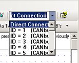
Hi all, something not quite right in the comms dropdown box. I recently moved up to 9.8.31/0 and all seems ok but the dropdown functions oddly. The characters become much larger during selection, and I can also edit them. I thought this might have been a fix of something I requested a while back, but the edit doesn't persist. Also, sometimes I can only get Direct Connection showing, the drop down doesn't work at all. The only thing I have as a pointer is that it seems to be related to opening something new, or opening after not finding a file where it used to be. You close and restart and the issue goes away. And an edit: I initially attached .bmps to this post, but they don't display as part of the post...just a link. Changed them to jpgs and they do. ?? cheers, Aus

-
I agree with go for serial. The extra cost of a dedicated panel like Cam suggests is often a far cheaper and better system than all the stuffing around and extra outputs needed for driving things directly. Been there, done that. In the old days I actually had to make the array from individual digits!! Aahhh..how I miss that....not! These days, youngsters are so spoilt! cheers, Aus


